Connecting
5.2 Transmitter Wiring
FUE1010 IP65 NEMA 4X
Operating Instructions, 12/2014, A5E03086491-AC
43
Wiring Temperature Sensor Board
1. Using a flat-blade screwdriver, loosen Terminal Block TB1 and TB2 screws.
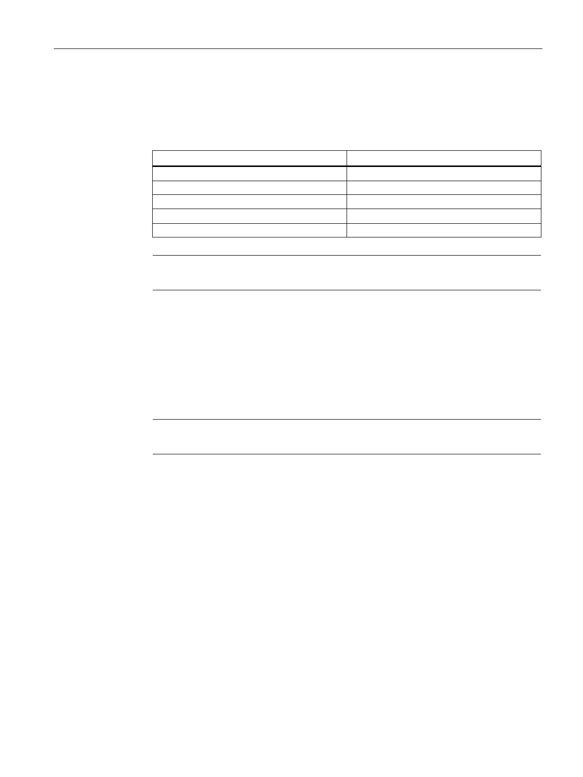
2. Wire the RTD liquid 992EC temperature cable as shown in the table below:
Wire #4 (Red) To TB1--4
Note
*For cathodically protected pipes, do not attach blue #5 wire at RTD end of cable.
3. For single channel use, wire TB2 as shown in figure above.
4. For dual channel use, connect Channel 2 temperature sensor to TB2.
5. Replace I/O Board and secure with four captive screws paying careful attention to pin
alignment.
6. Replace Access Cover and finger tighten captive thumbscrew.
7. Connect power cables to the appropriate power source (90-240 VAC @ 50-60 Hz or 9-36
VDC). Close cover
Note
TB3 and TB4 are also act
ive analog inputs. See wiring table below.
Supply and Return Connections
Terminals for the supply and return sensor connections are located on the Analog Input
Module as previously shown. For other terminal locations on Single Channel and Dual
Channel units, refer to drawings 1010N-5-7 or 1010N-5D-7, respectively. For terminal
locations on Multi-Channel units, refer to drawing 1010N-8M-7.

 Loading...


