Scale parameters and functions
8.18 DR 18 digital output control specifications
SIWAREX WP231
Manual, 07/2014, A5E31238908A-02
111
DR 18 digital output control specifications
8.18.1
If a digital output is defined in data record DR 7 for control with data record DR 18 (see
Assignment for digital output 0, 1, 2, 3 (Page 92)), you can control this output with data
record DR 18. Transfer is always for all four digital outputs. Only outputs which are
configured for control by DR 18 (see DR 7 interface parameters (Page 88)) are enabled or
disabled in accordance with the content of data record DR 18.
● Check or adapt the desired parameter settings of the digital outputs in data record 7
● Define the value for digital output 0, 1, 2, 3
● Transfer the data record to the scales
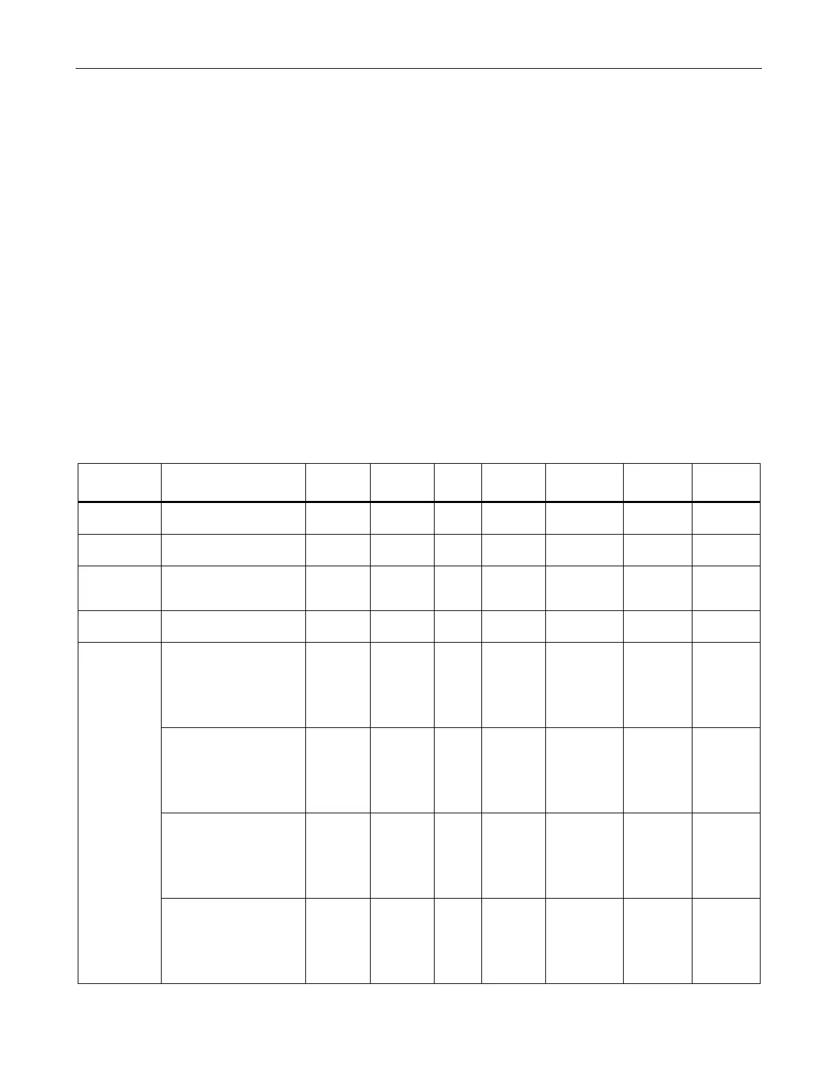
Table 8- 19 Assignment of data record 18
Data record
number
Contains no. of data record USHORT 2 r 18 - - 1608
Length Data record length infor-
mation
USHORT 2 r 12 - - 1609
Application Information about which
application the DR belongs
to
USHORT 2 r 101 - - 1610
Version identi-
fier
Information on current data
record version
USHORT 2 r 1 1 65635 1611
Specification
for digital
output 0, 1, 2,
3 (Page 113)
Specification for digital
output 0=1 -> DA0 output
enabled
(only applies if output is
assigned code 21, see
DR 7)
BIT 0 rw 0 0 1 1612.16
Specification for digital
output 1=1 -> DA1 output
enabled
(only applies if output is
assigned code 21, see
DR 7)
BIT 0 rw 0 0 1 1612.15
Specification for digital
output 2=1 -> DA2 output
enabled
(only applies if output is
assigned code 21, see
BIT 0 rw 0 0 1 1612.14
Specification for digital
output 3=1 -> DA3 output
enabled
(only applies if output is
assigned code 21, see
DR 7)
BIT 0 rw 0 0 1 1612.13