Section 04 TRANSMISSION
Sub-Section 02 (DRIVE BELT)
04-02-3
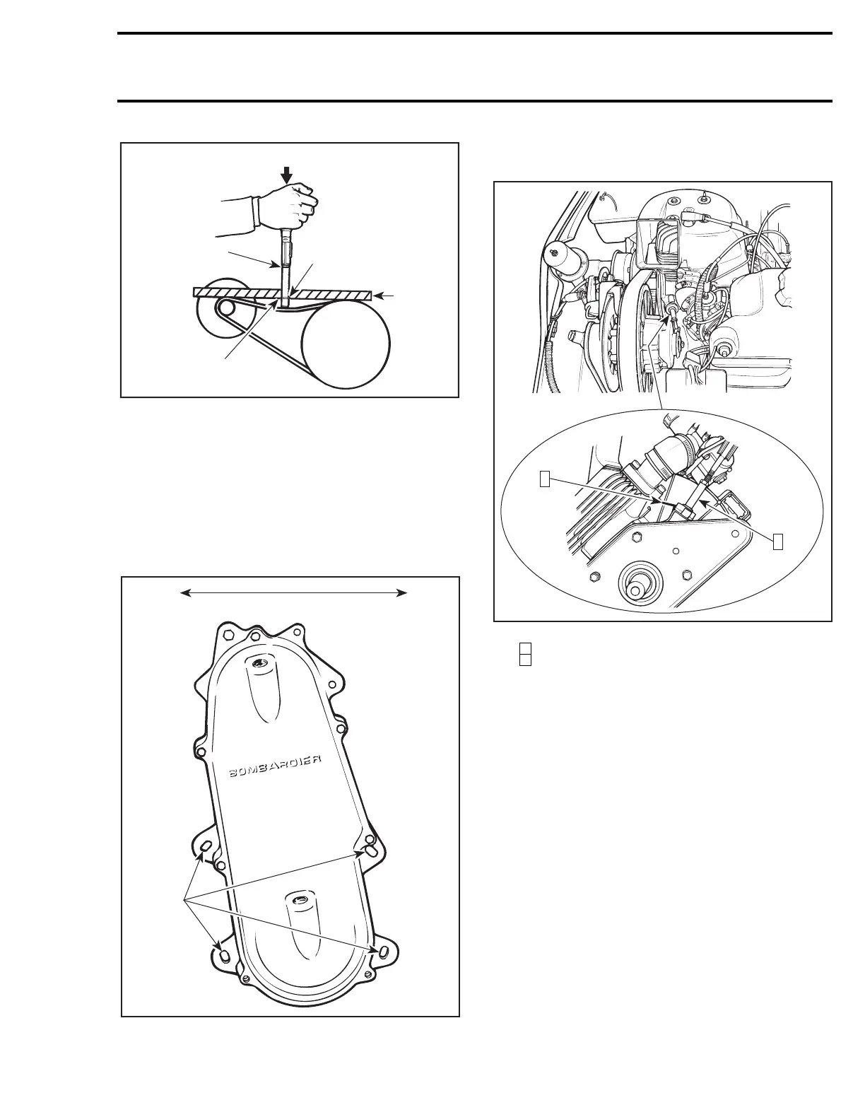
1. Upper O-ring
2. Force
3. Lower O-ring
4. Reference rule
5. Deflection
DEFLECTION ADJUSTMENT 2
Tundra II LT
Drive belt deflection is adjusted by moving chain-
case.
TYPICAL
1. Movement
2. Retaining nuts
To do so, loosen the 4 chaincase retaining nuts,
unlock and raise driven pulley support.
TUNDRA II LT
Step : Push and hold
Step : Raise support
Adjust pulley distance according to specification,
refer to PULLEY DISTANCE AND ALIGNMENT
04-05 and measure drive belt deflection. Readjust
pulley distance if required, then tighten the 4 nuts.
Adjust driven pulley support and lock it to engine.
S-Series
Adjust pulley distance according to specification,
refer to PULLEY DISTANCE AND ALIGNMENT
04-05, then adjust drive belt deflection using Allen
screws, as shown.
To increase deflection : turn Allen screws clock-
wise.
To decrease deflection : turn Allen screws coun-
terclockwise.
NOTE :
Turn Allen screws 1/4 turn at a time,
then rotate driven pulley to allow drive belt
to settle in pulley. Check deflection, repeat as re-
quired.
A00D08A
2
1
3
4
5
A07D11A
1
2
A05D0PA
2
1
1
2
'
 Loading...
