Section 04 TRANSMISSION
Sub-Section 04 (DRIVEN PULLEY)
04-04-2
NOTE :
Driven pulley components (support,
cam, shoes, etc.) can be serviced without re-
moving the whole driven pulley from chaincase.
Refer to the following procedures but neither re-
move brake caliper nor open chaincase for those
cases.
REMOVAL
To remove driven pulley from chaincase, follow
this procedure.
Remove belt guard and drive belt from vehicle.
Remove brake support
no. 13
from chaincase
with brake ass’y.
Free countershaft support
no. 1
from support
clamp.
To remove driven pulley support use support pull-
er (P / N 529 0135 00).
Chaincase
Open chaincase and drain oil. Unlock and remove
upper sprocket.
The following is required to have enough space to
remove driven pulley from chaincase :
Slacken upper retaining screws of steering col-
umn.
Disconnect carburetor boots from intake manifold
and air intake silencer.
Disconnect impulse hose from engine.
Disconnect oil injection supply line at injection
pump and plug line to prevent draining.
Remove screws retaining rear engine support to
chassis.
Tip engine forward just enough to allow driven
pulley removal from chaincase. Block in this posi-
tion.
NOTE :
In some cases, chaincase retaining
screws might have to be slackened to allow
pivoting of chaincase. In this case, note position
of alignment shims. Besides, air intake silencer
and oil injection reservoir might have to be slightly
moved to get enough space to pull driven pulley.
DISASSEMBLY
Chaincase and Driven Pulley
Remove bearing cone.
Knock driven pulley shaft with a plastic hammer
and pull driven pulley out.
Remove support
no. 1
using a suitable puller.
Remove roll pin
no. 2
and slide outer cam
no. 4
out of pulley shaft.
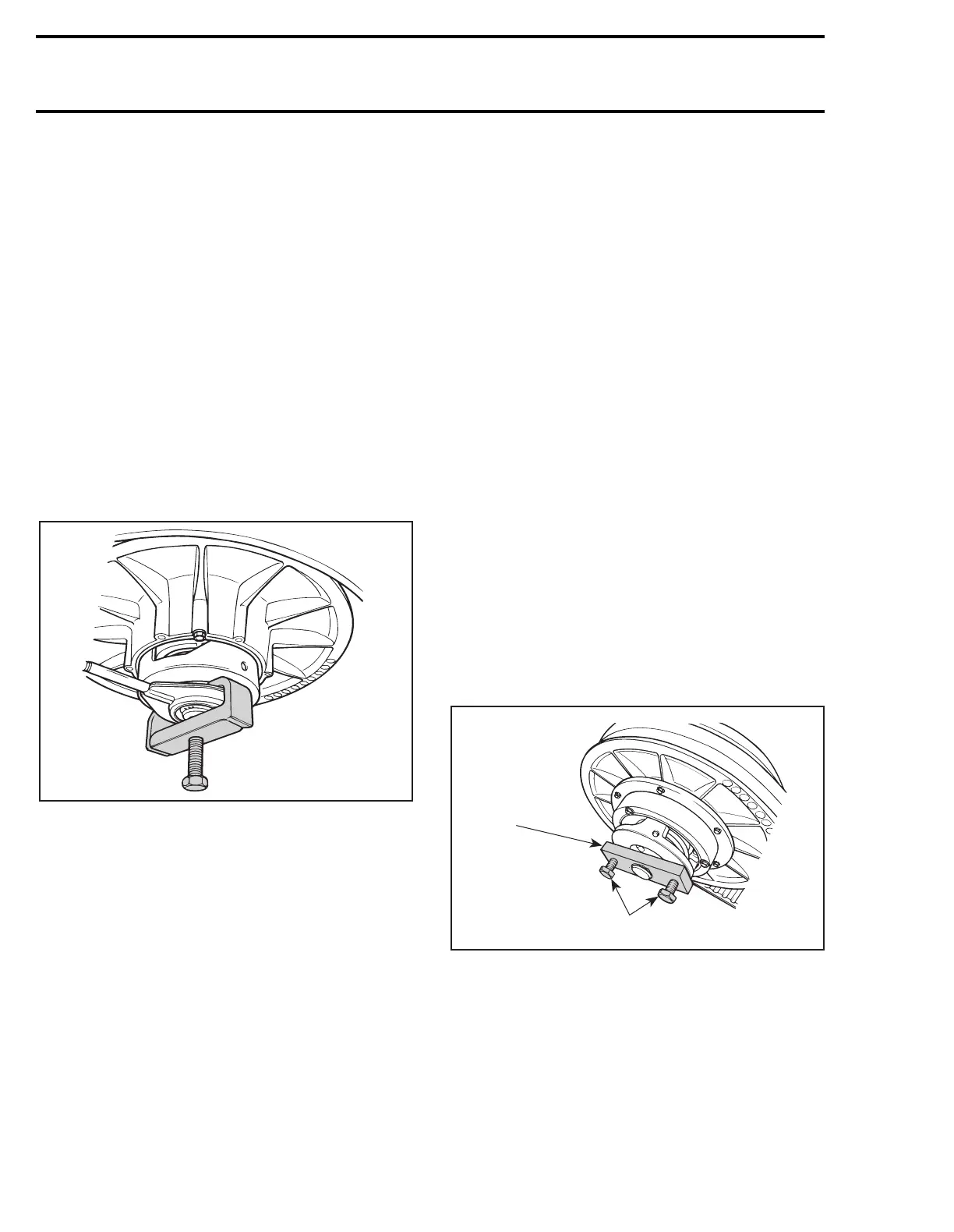
Install tool (P / N 529 0129 00), reinstall washer,
lock washer and screw. Tighten tool screws alter-
nately then remove roll pin.
1. Tighten alternately
Note spring original setting (adjusting hole in slid-
ing half).
A25B0GA
529 0135 00
'
A18B07A
529 0129 00
1