Section 04 TRANSMISSION
Sub-Section 06 (BRAKE)
04-06-4
REMOVAL
Tundra II LT
The split caliper type brake should be removed
from chaincase as an assembly. Proceed as
follows :
– Remove belt guard.
– Disconnect brake cable.
– Remove bolts
no. 8
securing brake support to
chaincase.
– Slide brake caliper ass’y out of brake support.
– To remove brake disc, refer to DRIVEN PULLEY
04-04.
BRAKE DISC REMOVAL
S-Series with Mechanical Brake
Brake disc can be withdraw without removing cal-
iper. Proceed as follows :
– Remove belt guard, belt and driven pulley.
– Remove air silencer.
– Unbolt bearing support from chassis.
– Open chaincase and remove upper sprocket.
– Pull countershaft toward driven pulley side to
gain access to clip
no. 25
.
– Remove clip
no. 25
on countershaft.
– Pull countershaft toward driven pulley side tof-
ree from chaincase and disc.
– Remove disc.
COUNTERSHAFT REMOVAL
S-Series with Mechanical Brake
Proceed the same as for brake disc removal but
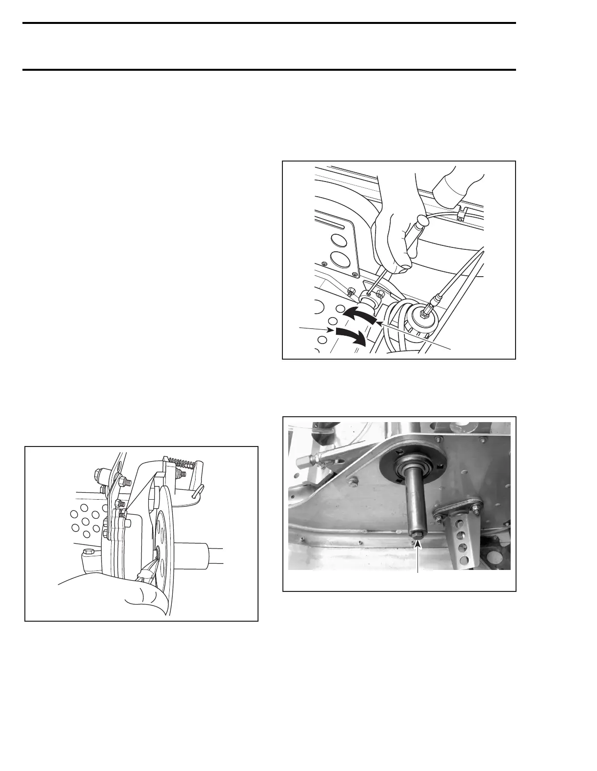
unlock bearing collar on driven pulley side.
1. Lock
2. Unlock
Unbolt bearing support then install screw on
countershaft.
1. Screw
Push bearing to driven pulley side out of counter-
shaft, using remover (P / N 529 0301 00). Begin
with only the remover then add a spacer of differ-
ent width as the bearing comes out.
A03D11A
A06D18A
1
2
A03D29A
1