Section 07 STEERING / FRONT SUSPENSION
Sub-Section 02 (STEERING SYSTEM)
07-02-5
ADJUSTABLE HANDLEBAR
1,3, Steering Column and Handlebar
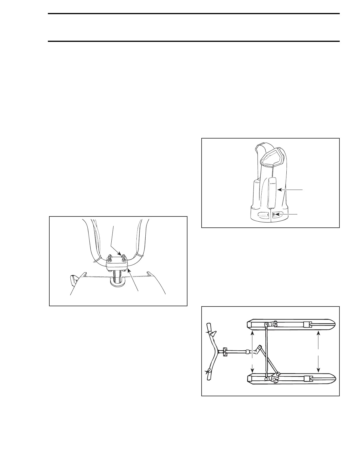
If applicable, remove the steering clamp and nuts
holding the handlebar to the steering column.
Tighten nuts to the specified torque (see illustra-
tion).
2,4,5,6, Handlebar Support, Steering
Clamp, Bolt and Nut
Install the four handlebar support, steering clamp,
the four screws and nuts to the column, as illus-
trated.
See applicable exploded view for each model.
Adjust the steering handle to the desired position.
Lock the handle in place by tightening the four
nuts to 26 N•m (19 lbf•ft).
CAUTION : Tighten the nuts equally in a
criss-cross sequence and ensure there is
an equal gap on each side of the clamps.
TYPICAL
1. Torque 26 N•m (19 lbf•ft)
2. Equal gap all around
WARNING : Avoid contact between the
brake handle and the windshield by
NOT
adjusting the handlebar too high.
WARNING : Make sure that the steering
pad and all controls are properly fixed to
their normal location on the handlebar.
CAUTION : Plastic alloy components such
as fuel tank, windshield, controls, etc. can
be cleaned using mild detergents or isopropyl
alcohol and a soft clean cloth. Never clean
plastic parts with strong detergent, degreasing
agent, paint thinner, acetone, etc. Do not apply
isopropyl alcohol directly on decals.
7,23,24,25, Steering Pad, Bolt, Nut and
Rubber Attachment
CAUTION : Prior to installation, perform han-
dlebar adjustment.
Properly fit the steering pad to the handlebar. As-
semble using the two rubber attachments, nuts
and bolts.
WARNING : Make sure that the steering
pad and all controls are properly fixed to
their normal location on the handlebar.
1. Rubber attachment
2. Nut and bolt
STEERING ADJUSTMENT (SKIS)
Definitions
TOE-OUT:
A difference in measurement between front edge
A and rear edge B of skis as viewed from top side
of suspension system. It is adjustable.
1
2
A08G05A
;
;
;
A09G05A
1
2
A01G04A
B
A
B
A