03-1
Section 03 ELECTRICAL SYSTEM
ELECTRICAL SYSTEM 0
360-WATT MAGNETO
SYSTEM
COMPONENT LOCATION
Refer to photos included with the electrical dia-
gram.
THEORY AND OPERATION
Charging System
Lighting Coil
This 360-watt coil produces alternating current.
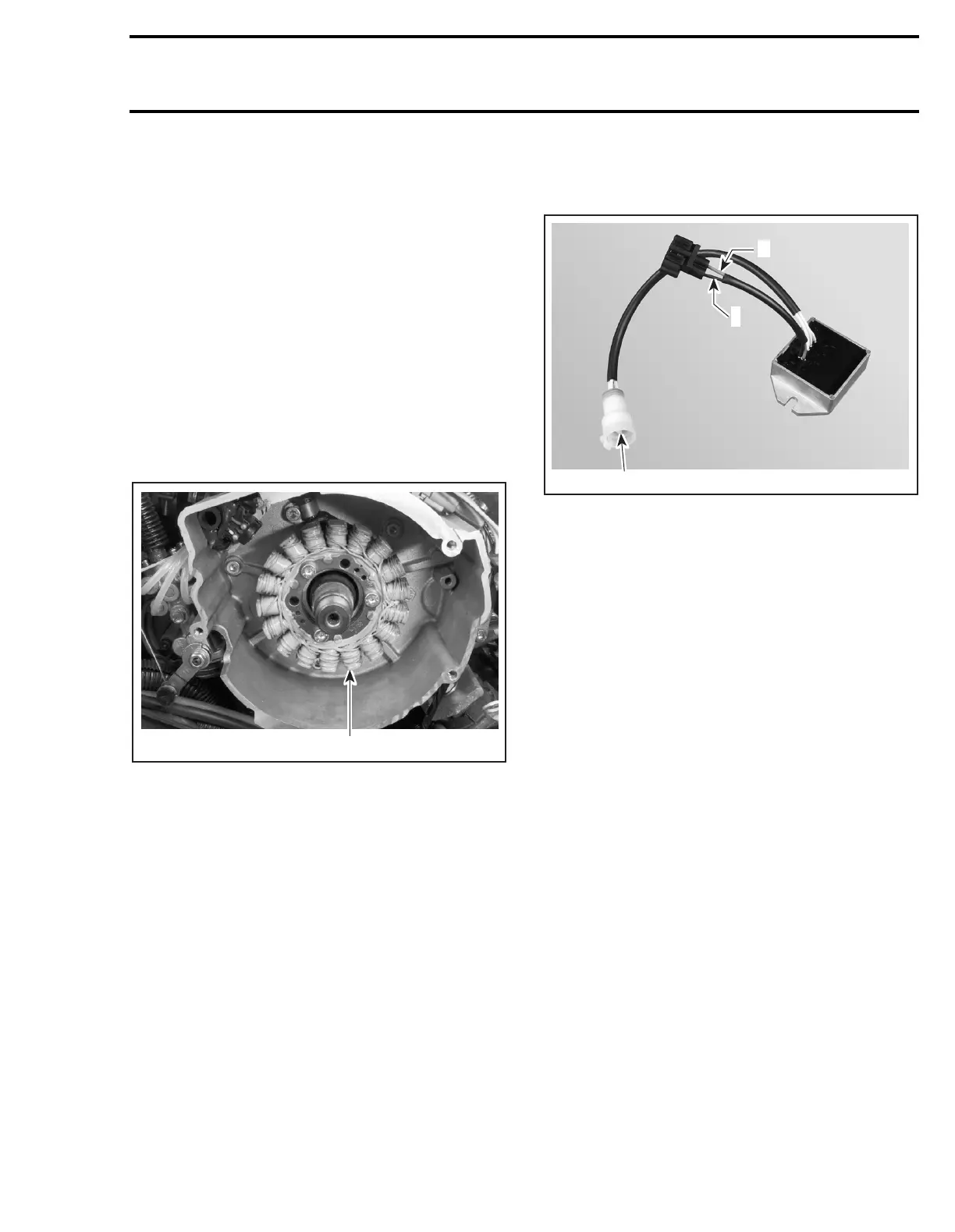
360-WATT MAGNETO
1. Triple coil (3-phase)
Regulator/Rectifier
First, the regulator/rectifier converts the alternat-
ing current of the magneto into direct current
(DC).
It uses diode bridges allowing the alternating cur-
rent to pass in one direction only.
The negative (-) wire (black) is connected to
ground (regulator housing) and to the frame, while
the positive wire is RED/BLUE.
+ Positive
- Negative
1. Magneto
All accessories are fed with direct current.
NOTE:
The tachometer receives a very small por-
tion of the alternating current through the
WHITE/GREEN wire. The tachometer must de-
tect a variable pulse (alternating current) to oper-
ate. Note that it is the only accessory fed with
alternating current but operating on direct current.
After rectifying the magneto current, the regulator/
rectifier limits the magneto voltage to 14.7 volts.
NOTE:
In simpler terms, an electrical system pro-
ducing 14.7 volts is called a 12-volt system.
A00E4XA
1
A00E51A
1
-
+
 Loading...
