Section 05 ELECTRICAL
Sub-Section 07 (TESTING PROCEDURE)
05-07-7
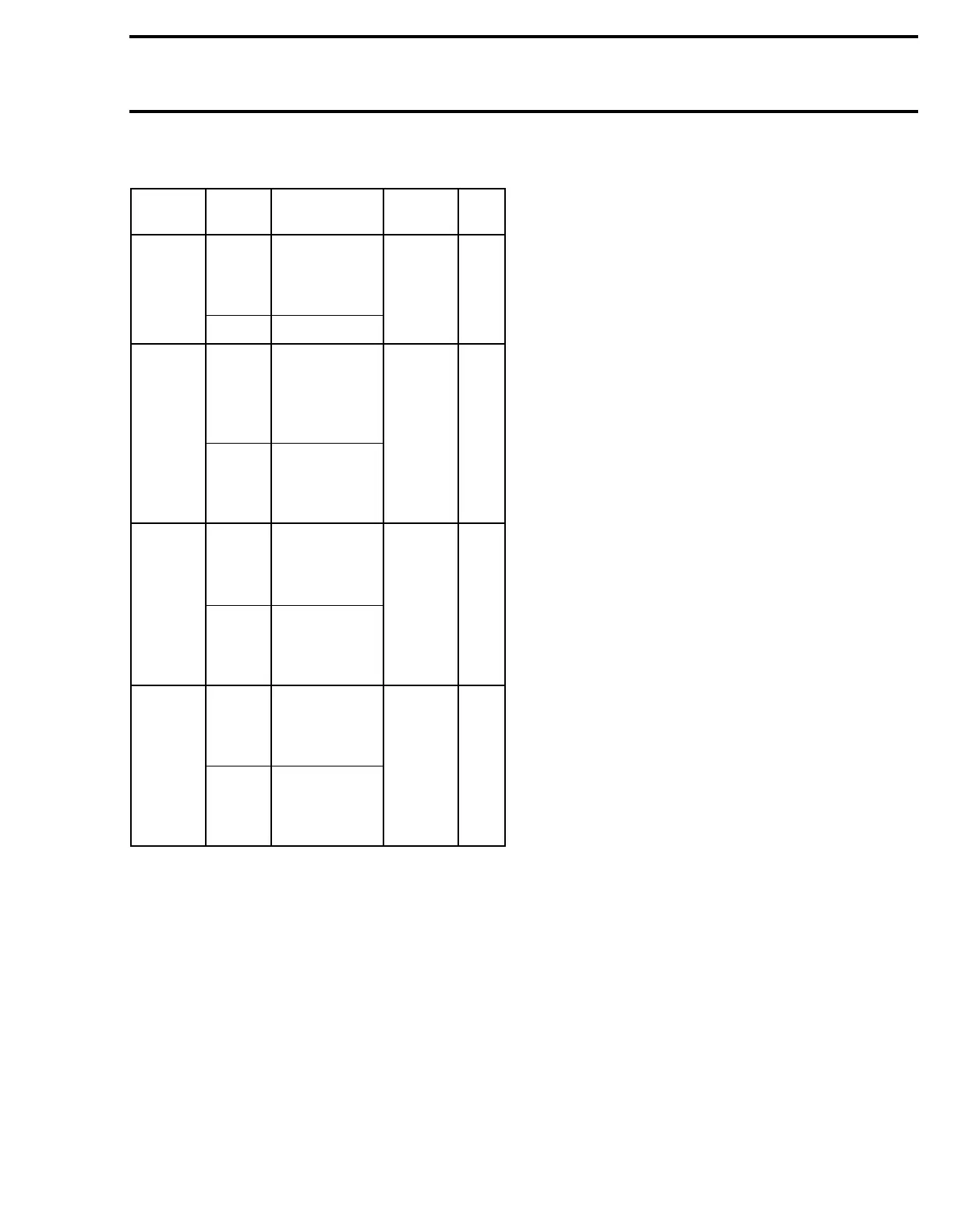
SUMMARY TABLE RESISTANCE MEASUREMENTS
As an alternate method, magneto system compo-
nents can be checked with a digital ohmmeter.
NOTE :
All resistance measurements must
be performed with parts at room tempera-
ture (approx. 20°C (68°F)). Temperature greatly af-
fects resistance measurements.
Disconnect connectors at ignition coil and magne-
to junction. Measure resistance between each
terminal. Refer to the following table for values
and wire colors.
NOTE :
An ignition coil with good resistance
measurement can still be faulty. Voltage leak
can occur at high voltage level which is not detect-
able with an ohmmeter.
Test to
perform
Tester
wires
Component
wires
Switch Dial
Ignition
coil
output
N
Test adapter
on MAG
spark plug
cable
LOW 45
P Engine ground
Ignition
module
output
N
WHITE
/
BLUE
wire (
+
)
of ignition
coil
HIGH 55
P
BLACK
wire (
−)
of ignition
coil
Magneto
output
(ignition
generator
coil)
N
BLACK
/
RED
wire of
magneto
harness
LOW 85
P
BLACK
wire of
magneto
harness
Lighting
generator
coil
output
N
YELLOW
wire of
magneto
harness
LOW 70
P
YELLOW
wire of
magneto
harness
'