Section 04 TRANSMISSION
Sub-Section 03 (DRIVE PULLEY)
04-03-6
Press bushing.
1. Note upper tool side.
ASSEMBLY
NOTE:
This drive pulley is lubrication free.
Do not lubricate
any component.
1,2,3, Screw, Ring Gear and Loctite 271
Apply Loctite 271 (P/N 413 7029 00) on threads
and then torque to 27 N•m (20 lbf•ft).
26,27,28, Calibration Screw, Washer
and Locking Nut
When installing calibration screw, make sure to in-
stall washer as shown.
1. Washer
Torque locking nut to 10 N•m (89 lbf•
in
).
15, Pin
Always use the same type of pin as originally in-
stalled when servicing. Different types have dif-
ferent weights for calibration purpose. Refer to
TECHNICAL DATA 09-03.
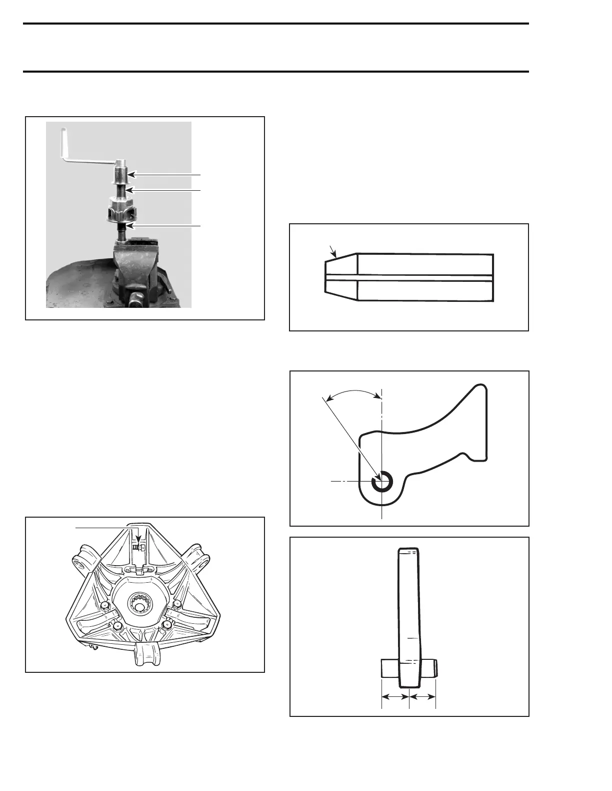
21,22,23, Ramp, Dowel Tube and Screw
Insert dowel tube from chamfered side. Make
sure ramp is centered on dowel tube.
1. Chamfered side
Position dowel tube split at the illustrated angle.
1. Equal distance
Torque screws to 10 N•m (89 lbf•
in
).
A01D2OA
529 0313 00
529 0312 00
1
'
A16D07A
1
A16D08A
1
A16D2PA
30 ± 5°
A16D09A
11