Section 03 ENGINE
Sub-Section 05 (CDI SYSTEM)
03-05-2
NOTE :
The following procedures can be
done without removing the engine from
chassis.
CLEANING
Clean all metal components in a non-ferrous met-
al cleaner.
CAUTION : Clean armature and magneto
using only a clean cloth.
DISASSEMBLY
To gain access to magneto assembly, remove the
following parts as needed on different engines :
– tuned pipe and muffler
– oil injection pump mounting plate from rewind
starter
– rewind starter
– starting pulley
no. 10
and fan
no. 11
To remove magneto flywheel retaining nut
no. 13
,
install puller ring (P / N 420 8760 80) and M8 x 20
screws.
– Remove magneto flywheel nut, using a 30 mm
socket machined to 40 mm (1.580 in) outside
diameter by 16 mm (5/8 in) long.
NOTE :
To correctly remove a threadlocked
fastener it is first necessary to tap on the fas-
tener to break threadlocker bond. This will
eliminate the possibility of thread breakage.
TYPICAL
1. 30 mm socket
To remove magneto flywheel
no. 9
, install the
magneto puller (P / N 529 0225 00).
TYPICAL
– Tighten puller bolt and at same time, tap on bolt
head using a hammer to release magneto fly-
wheel from its taper.
NOTE :
Before disassembling armature
plate, indexing marks should be scribed to
facilitate reassembly.
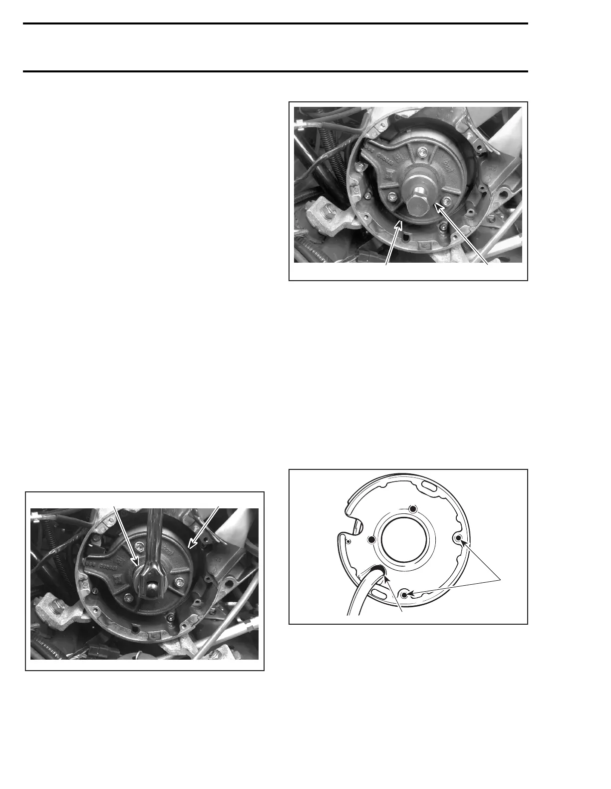
REPAIR
To replace generator coil
no. 2
:
– Heat the armature plate to 93°C (200°F) around
the screw holes to break the threadlocker
bond.
1. Heat
2. Protect harness from flame
CAUTION : Protect harness from flame.
– Remove screws.
– Uncrimp and unsolder BLACK/RED wire from
coil terminal.
A03C1JA
420 8760 80
1
A03C07A
529 0225 00420 8760 80
'
A01C03A
1
2