Section 03 ENGINE
Sub-Section 04 (LEAK TEST AND ENGINE DIMENSION MEASUREMENT)
03-04-6
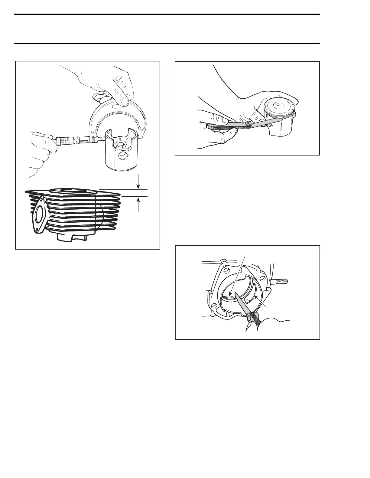
A. 16 mm (5/8 in)
The difference between these 2 measurements
should be within specified tolerance. Refer to
TECHNICAL DATA 09-02.
Measurement (fitting new parts)
With an inside micrometer, measure cylinder di-
ameter above the exhaust port.
With a micrometer, measure the piston diameter
perpendicularly (90°) to piston axis and 3 mm (1/8
in) above bottom edge.
The difference of both measurements is the clear-
ance.
RING / PISTON GROOVE
CLEARANCE
Using a feeler gauge check clearance between
rectangular ring and groove. Replace piston. If
clearance exceeds specified tolerance. Refer to
TECHNICAL DATA 09-02.
RING END GAP
Position ring half way between transfer ports and
intake port. On rotary valve engines, position ring
just below transfer ports.
NOTE :
In order to correctly position the ring
in the cylinder, use piston as a pusher.
Using a feeler gauge, check ring end gap. Replace
ring. If gap exceeds specified tolerance, refer to
TECHNICAL DATA 09-02.
1. Transfer port
2. Intake port
CRANKSHAFT DEFLECTION
Crankshaft deflection is measured with a dial indi-
cator.
Measuring (In Engine)
First, check deflection with crankshaft in engine.
If deflection exceeds the specified tolerance, re-
check deflection using V-shaped blocks to deter-
mine the defective part(s). See below.
A
A01C55A
A01C0PA
A01C0QA
2
1