Section 03 ENGINE
Sub-Section 11 (CARBURETOR AND FUEL PUMP)
03-11-3
DISASSEMBLY AND ASSEMBLY
NOTE:
To ease the carburetor disassembly
and assembly procedures it is recommend-
ed to use carburetor tool kit (P/N 404 1120 00).
2,3, E-clip and Needle
Remove screws from needle retaining plate to
withdraw the needle.
The position of the needle in the throttle slide is
adjustable by means of an E-clip inserted into 1 of
5 grooves located on the upper part of the needle.
Position 1 (at top) is the leanest, 5 (at bottom) the
richest.
NOTE:
The last digit of the needle identifica-
tion number gives the recommended posi-
tion of the E-clip
from the top
of the needle.
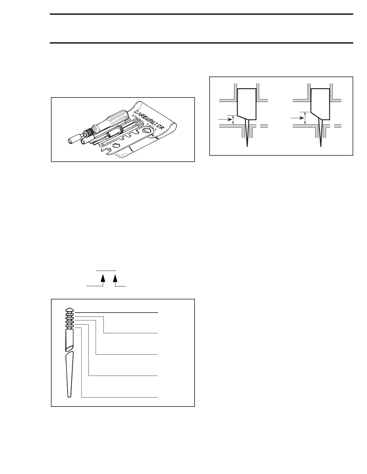
CLIP POSITIONS
The size of the throttle slide cut-away affects the
fuel mixture between 1/8 to 1/2 throttle opening.
1. Low cut-away low
2. Rich mixture
3. High cut-away high
4. Lean mixture
8, Main Jet
The main jet installed in the carburetor has been
selected for a temperature of -20°C (0°F) at sea
level. Different jetting can be installed to suit tem-
perature and/or altitude changes. Always check
spark plug tip and/or piston dome color to find out
correct jetting.
CARBURETOR FLOAT LEVEL
ADJUSTMENT
9,10, Float Arm and Float Arm Pin
Correct fuel level in float chamber is vital toward
maximum engine efficiency. To check for correct
float level proceed as follows:
– Make sure that float arm is symetric — not dis-
tored.
– Remove float bowl and gasket from carburetor.
– With carburetor chamber upside-down on a lev-
el surface, measure height H between bowl
seat and
top
edge of float arm. Keep ruler per-
fectly vertical and in line with main jet hole.
Example: 6DH4-3
Needle
identification
Recommended position.
of the E-clip from top
'
A00B2FA
'
A00B2GA
1
2
3
4
5
Lean
Rich
1
3
2
4
A00C01A
 Loading...
