Section 05 ELECTRICAL
Sub-Section 07 (TESTING PROCEDURE)
05-07-10
DUCATI CDI SYSTEM TESTING
(Applicable to 443 and 503 Engine Types)
NOTE:
Ensure ignition cut-out switches are
properly working and they are in the ON po-
sition prior to performing the following tests.
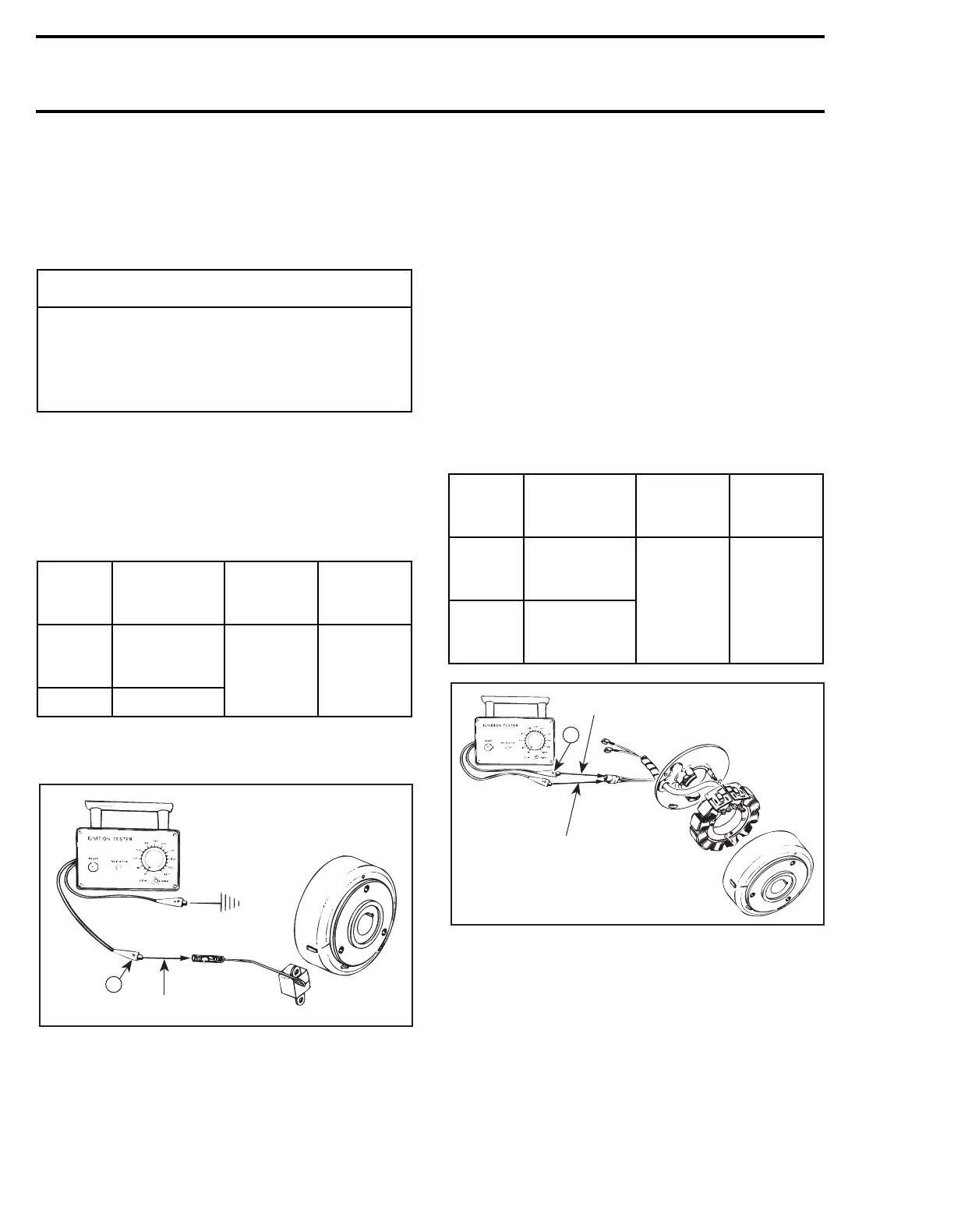
TRIGGER COIL OUTPUT
1. Disconnect the connector of RED wire at igni-
tion module.
2. Connect tester wires then set switch and dial
as follows:
3. Crank engine and observe indicator.
4. Push reset button and repeat step 3 twice.
1. Engine ground
2. White/Red
Results:
a.
Indicator lamp lights:
Trigger coil output is
up to specifications.
b.
Indicator lamp does not light:
The problem
is a faulty trigger coil or bad grounding.
MAGNETO OUTPUT
(Ignition Generator Coil)
1. Disconnect the 2-wire connector between igni-
tion module and magneto harness.
2. Connect tester wires then set switch and dial
as follows:
1. Green
2. White
3. Crank engine and observe indicator.
4. Push reset button and repeat step 3 twice.
Results:
a.
Indicator lamp lights:
Ignition generator coil
output up to specifications.
b.
Indicator lamp does not light:
The problem
is a faulty ignition generator.
◆
WARNING
To prevent powerful electric shocks while
cranking engine, do not touch neither elec-
tronic ignition components (ignition coil,
high tension wire, wire harness, etc.) nor
tester leads.
Tester
wires
Component
wires
Tester
switch
position
Tester
dial
position
N
WHITE/RED
wire of
trigger coil
LOW 45
P Engine ground
'
N
A17E0UA
1
2
Tester
wires
Component
wires
Tester
switch
position
Tester
dial
position
N
GREEN
wire of
magneto harness
LOW 80
P
WHITE
wire of
magneto harness
A17E0VA
1
2
N