Section 05 ELECTRICAL
Sub-Section 07 (TESTING PROCEDURE)
05-07-4
NIPPONDENSO CDI TRIGGER COIL SYSTEM TESTING
Applicable to 454, 494, 583 and 670 Engine
Types
NOTE:
Ensure ignition cut-out switches are
properly working and they are in the ON po-
sition prior to performing the following tests.
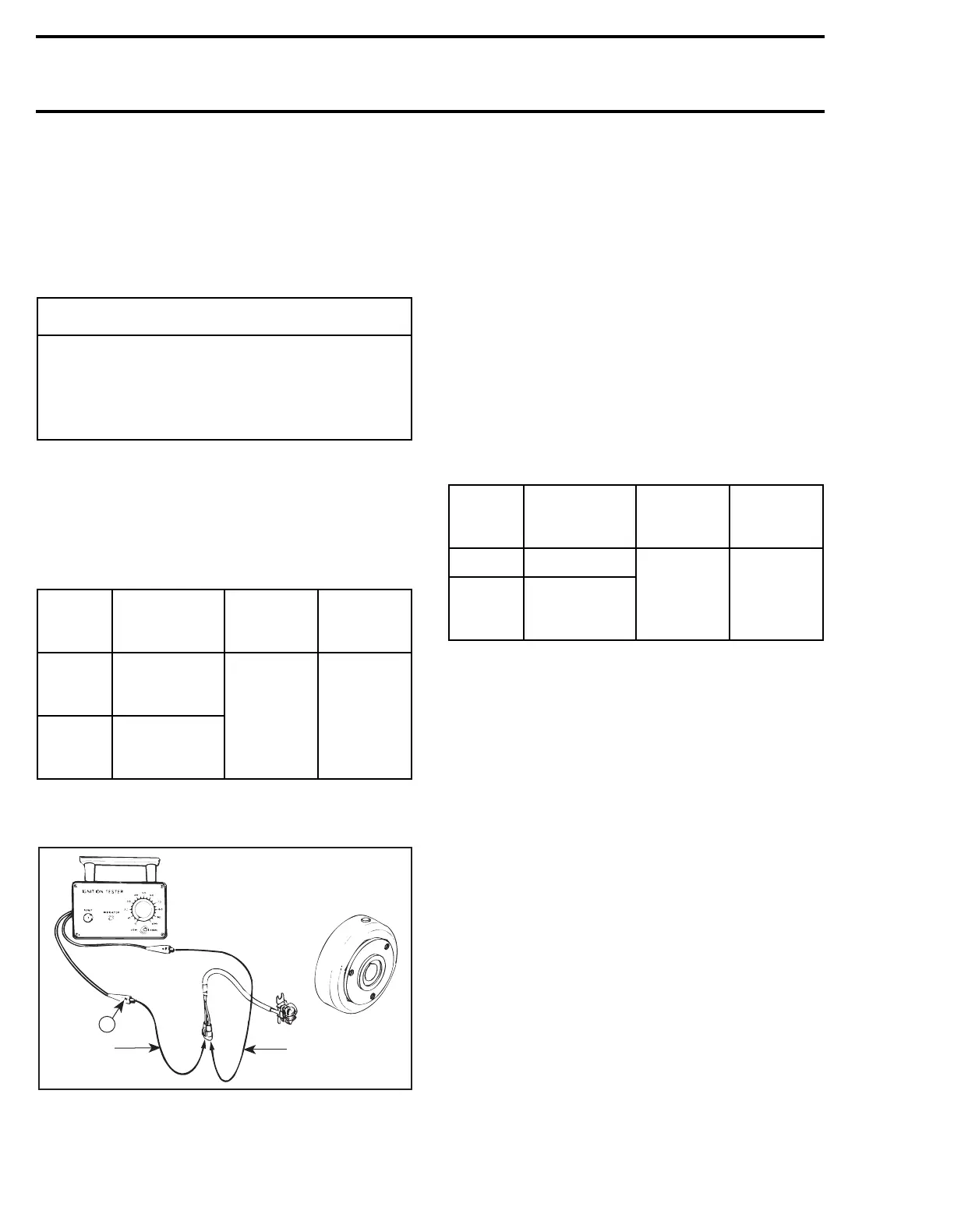
TRIGGER COIL OUTPUT
1. Disconnect connector housing of trigger coil at
ignition module.
2. Connect tester wires then set switch and dial
as follows:
3. Crank engine and observe indicator.
4. Push reset button and repeat step 3 twice.
TYPICAL
Results:
a.
Indicator lamp lights:
Trigger coil output is
up to specifications.
b.
Indicator lamp does not light:
The problem
is a faulty trigger coil or bad grounding.
IGNITION COIL OUTPUT
A paper clip of approximately 20 mm (3/4 in) will
be used as a test adapter for the following test.
1. Install the test adapter to spark plug cable close
to MAG side spark plug.
2. Connect tester wires then set switch and dial
as follows:
NOTE:
Different reading occurs if N tester
wire is connected to PTO or MAG side spark
plug cable.
◆
WARNING
To prevent powerful electric shocks while
cranking engine, do not touch neither elec-
tronic ignition components (ignition coil,
high tension wire, wire harness, etc.) nor
tester leads.
Tester
wires
Component
wires
Tester
switch
position
Tester
dial
position
N
BLUE/YELLOW
wire of
trigger coil
LOW
15
P
WHITE/YELLOW
wire of
trigger coil
'
A15E0RA
N
Blue/
Yellow
White/
Yellow
Tester
wires
Component
wires
Tester
switch
position
Tester
dial
position
N Engine ground
LOW
45
P
Test adapter
(paper clip)
spark plug cable
'