Section 03 ENGINE
Sub-Section 05 (CDI SYSTEM)
03-05-3
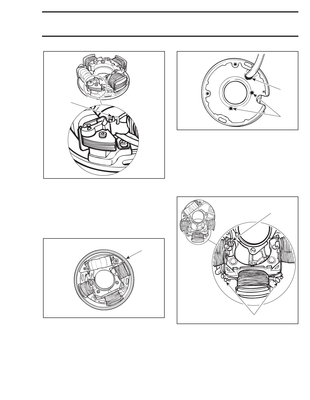
1. Uncrimp and unsolder wire here
– Strip end of old wire then crimp and solder on
new coil.
Apply Loctite 242 (blue) to screws
nos. 6
and
8
then install the new coil on armature plate.
Use magneto coil centering tool (P/N 420 8769
22) and install it so that it fits around armature
plate before tightening screws.
CAUTION : Before reinstalling the mag-
neto, remove the loose epoxy from har-
ness.
To replace lighting generator coil
no. 7
:
– Heat the armature plate to 93°C (200°F) around
the screw holes to break the threadlocker
bond.
1. Protect harness from flame
2. Heat
CAUTION : Protect harness from flame.
– Remove screws.
– Uncrimp and unsolder YELLOW and YELLOW/
BLACK wires from coil terminals.
– Uncrimp and unsolder ground wire (BLACK)
from coil core.
1. Uncrimp and unsolder ground wire (BLACK) here
2. Uncrimp and unsolder YELLOW and YELLOW/BLACK wires here
– Position new coil, crimp and solder all wires.
– Prior to assembly, apply Loctite 242 (blue).
Use magneto coil centering tool (P / N 420 8769
22) and install it so that it fits around armature
plate before tightening screws.
A25E0QA
1
A25E0RD
420 8769 22
A01C2JA
2
1
A25E0SA
1
2