CONTROLS
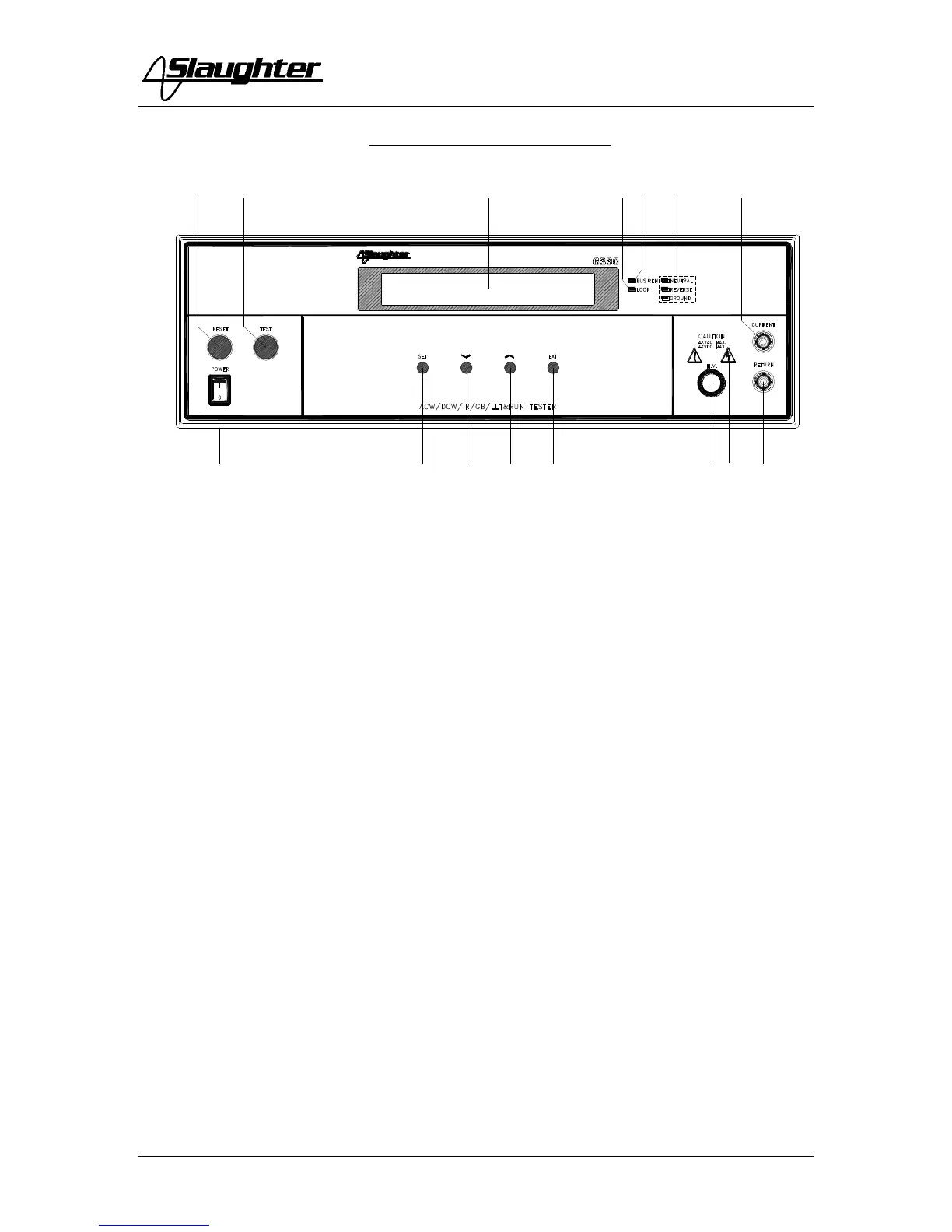
FRONT PANEL CONTROLS
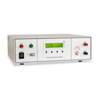
1. RESET BUTTON: This is a momentary contact switch used to reset the
instrument. If an out-of-range reading is detected during a test, the red failure lamp
within the button will light. To reset the system for the next test, press and release
this button. This button may also be used to abort a test in progress.
2. TEST BUTTON: This is a momentary contact switch used to start a test. Press the
green button to turn on the high voltage output when in test mode. The indicator
lamp within the button will light when test expires with pass condition.
3. LCD DISPLAY: The Liquid Crystal Display is the main readout for the operator
and programmer of the test settings and test results.
4. LOCK: This LED indicates that the Lock feature has been enabled.
5. BUS REMOTE INDICATOR: N/A
6. FAULT CONDITION INDICATORS: These LED’s indicate that the Neutral,
Reverse, and Ground Line Conditions have been activated during a Line Leakage
test.
7. CURRENT OUTPUT TERMINAL: This terminal is used for the connection of
the detachable 5-foot (1.52 m) red high current test lead. This terminal is always
used when performing a Ground Bond test.
8. POWER SWITCH: Rocker-style switch with international ON ( ) and OFF (0)
markings.
9. SET KEY: Use this key to advance forward through the setup menus.
10. DOWN ARROW (): Use this key to decrease the numeric values in the setup
mode. This key is also used to toggle ON/OFF functions. Also may be used to
decrease output voltage during a test in 10-volt increments.