CALIBRATION
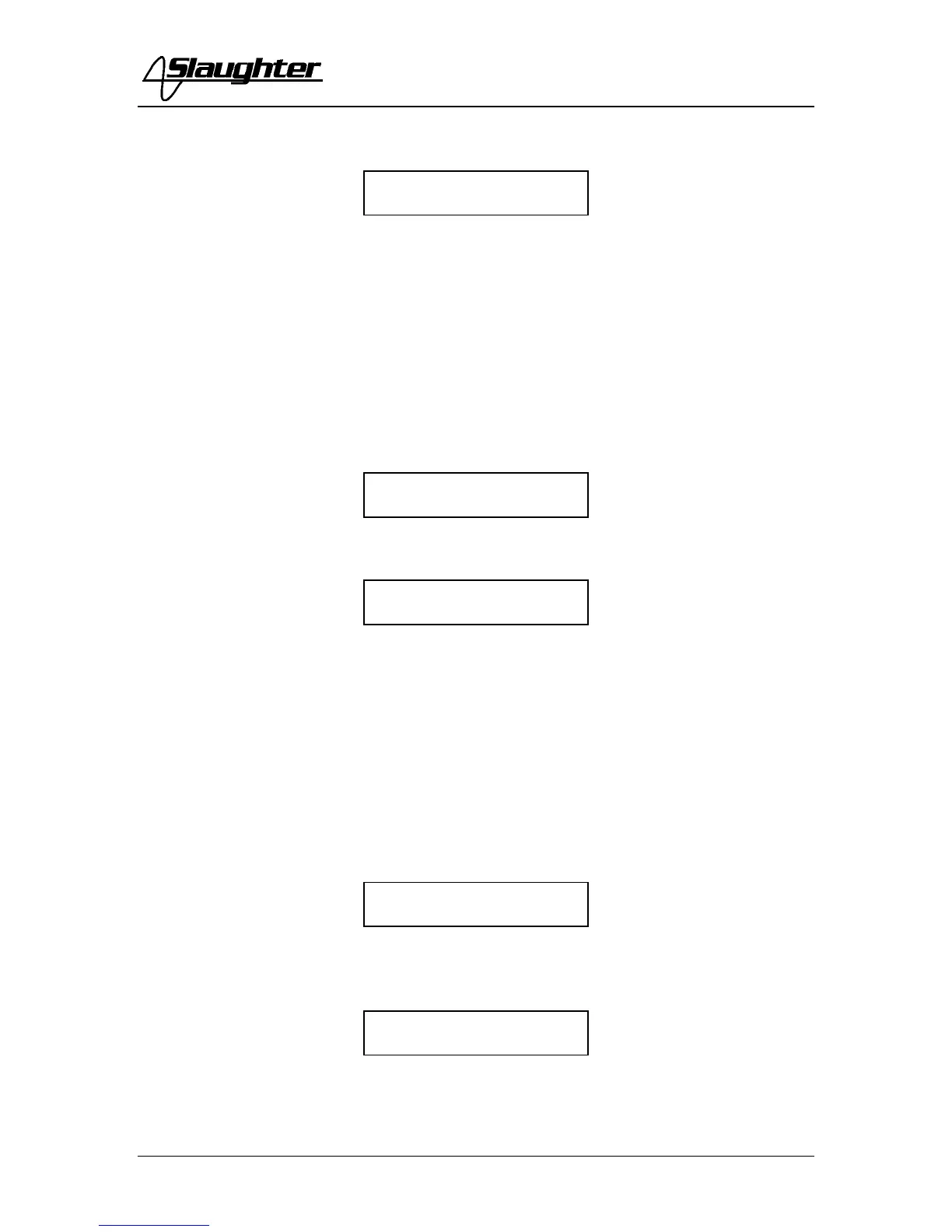
Then press the TEST button on the front panel and the display will show:
Then press SET key to advance to the next calibration point or press the RESET button to
return to the calibration menu without changing the calibration setting. Press the EXIT
key to exit from the calibration mode and to return to the test mode.
17. To calibrate the Line Leakage test x1
Please connect a standard voltmeter and DC power supply in parallel to the DUT Input
terminals. Place the power supply’s positive output (+) to the instrument’s Neutral
terminal. Place the power supply’s negative output (-) to the instrument’s Ground
terminal. Set the DC power supply to 8VDC.
Press the Up () or Down () arrow keys until the display shows:
Then press the TEST button on the front panel and the display will show:
Then press SET key to advance to the next calibration point or press the RESET button to
return to the calibration menu without changing the calibration setting. Press the EXIT
key to exit from the calibration mode and to return to the test mode.
18. To calibrate the Line Leakage test x4
Please connect a standard voltmeter and DC power supply in parallel to the DUT Input
terminals. Place the power supply’s positive output (+) to the instrument’s Neutral
terminal. Place the power supply’s negative output (-) to the instrument’s Ground
terminal. Set the DC power supply to 2VDC.
Press the Up () or Down () arrow keys until the display shows:
Then press the TEST button on the front panel and the display will show:
Then press SET key to advance to the next calibration point or press the RESET button to
return to the calibration menu without changing the calibration setting. Press the EXIT
key to exit from the calibration mode and to return to the test mode.
17. LLT X1
N/G Input 8.000VDC
18. LLT X2
N/G Input 2.000VDC