OPERATION
OPERATING PROCEDURES
Instrument Connections
If the instruments defaults are acceptable then be sure to connect the appropriate test
leads to the device under test (DUT) or test fixture. Be sure to connect the safety ground
(on the rear panel) to a suitable known good ground before energizing this instrument.
Connect the return lead to the test fixture or the DUT first, followed by the high voltage
lead.
Check your connections to be sure they are making good contact and that the test station
or area is clear of debris or other personnel.
DO NOT TOUCH THE DEVICE UNDER TEST ONCE
THE TEST HAS BEEN STARTED.
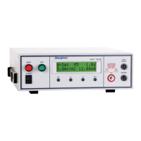
Display
Follow the previously stated setup procedures to set the desired parameters. The display
will show the Dielectric Withstand test settings, the Insulation Resistance test settings,
the Ground Bond test settings, the Functional Run test settings or the Line Leakage test
settings depending on what has been selected.
The underscore character may be displayed after the step number, i.e. X – X_. This
indicates that there is another configured test step that will execute after the displayed
setup has completed. To view the next test setup please press the SET key twice then
press the Up arrow key. To return to the previous test please press the Down arrow key
and then EXIT key to return to the test mode.
1. AC or DC Dielectric Withstand Test Mode
1.1. To initiate a test, press the TEST button on the front panel. The red High Voltage
Arrow indicator will flash and the display will immediately show:
or
DCW Set XXX.Xs
XX-XX X.XXkV XX.XXmA
DCW Dwell XXX.Xs
XX-XX X.XXkV XX.XXmA
The instrument will continue to output the desired voltage for the duration of the selected
Ramp and Dwell times.
1.2. If the DUT has passed the test, the green TEST button will illuminate and a short
audible beep tone will activate. The display will show:
ACW Set XXX.Xs
XX-XX X.XXkV XX.XXmA
ACW Dwell XXX.Xs
XX-XX X.XXkV XX.XXmA