(Model J) Page 297
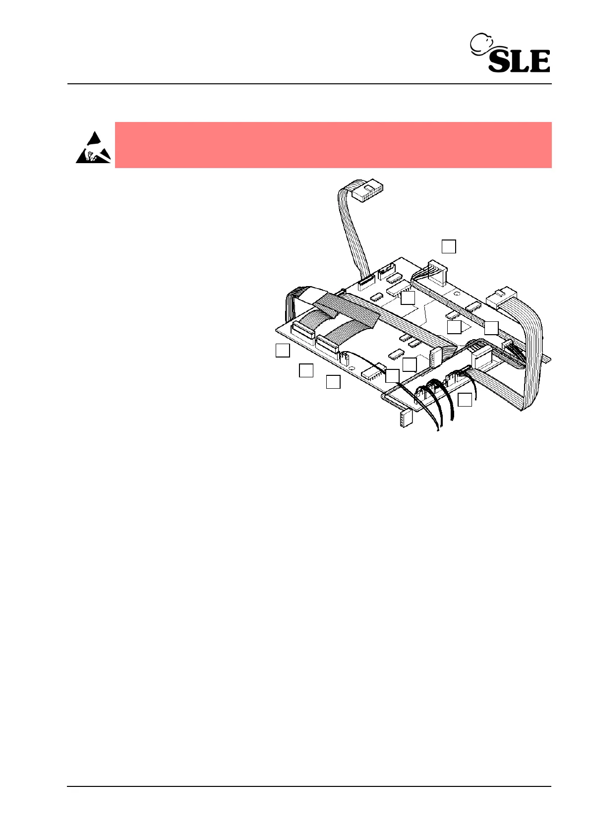
34.7.2 Control/Monitor Board removal
Step A17 Disconnect the following
cables.
Power supply connector
controller side, main loom
(A). (P4)
Controller to A0761
transducer assembly
ribbon cable (B). (P5)
Conventional valve drive
ribbon cable (C). (P6).
Analogue valve drive
ribbon cable (D). (P7)
Alarm sounder cable, main
loom (E). (JP5)
Battery/power supply sensing connector, main loom (F). (JP9)
Controller to A0761 transducer assembly connector (G). (JP7)
O
2
cell connector (H). (JP8)
Power supply connector monitor side, main loom (J). (JP6)
Flow sensor connector (K). (JP4)
Step 21 The control and monitor board can now be removed.
Step 22 Place the control and monitor to one side observing ESD precautions.
Warning: The Control/Monitor Board is a static sensitive device.