Page 296 (Model J)
34.7 EMC upgrade procedure
34.7.1 Disassembly
34.7.1.1 Computer/Display control assembly removal
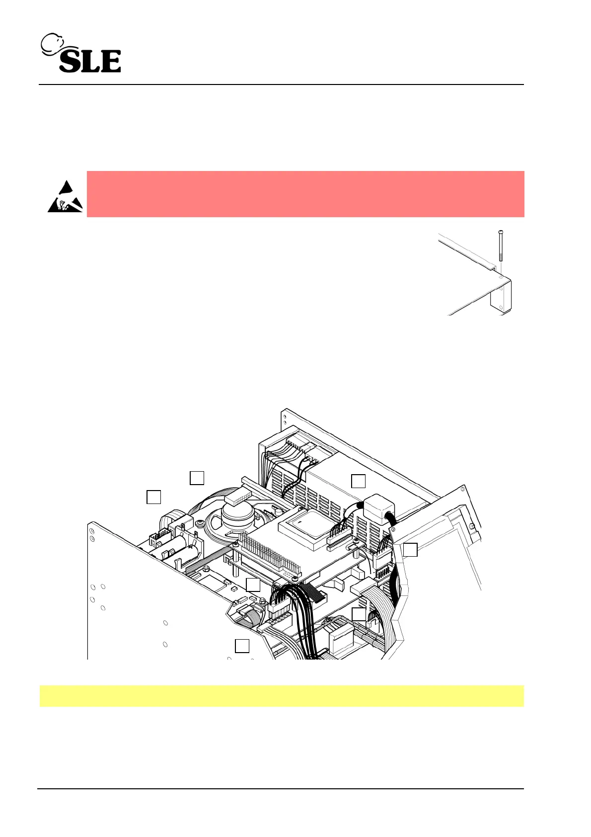
Step 12 Remove the PCB locking screw. This will allow the top board
assembly to slide forward a small amount which gives better
access to the edge connectors of the top board.
Step 13 Disconnect the display cable connector (A).
Step 14 Disconnect the touch screen connector cable connector (B).
Step 15 Disconnect the carrier board power cable connector (C).
Step 16 Disconnect the inverter board power cable connector (D).
Step 17 Disconnect the CAN card interface cables (E & F).
Step 18 Disconnect the RS232 connector cable (G).
Step 19 The carrier board can now be removed by sliding towards the rear of the ventilator
Step 20 Place the carrier board to one side observing ESD precautions.
Warning: The Computer/Display Control assembly is a static sensitive
device.
Note: L0275 assembly shown