(Model J) Page 35
8. Component Replacement (Electronic unit)
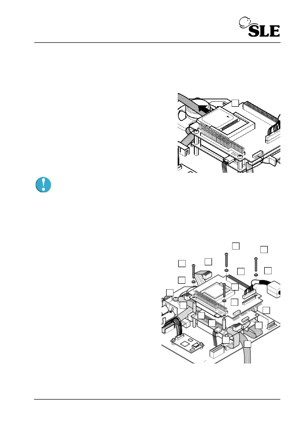
8.1 N6631/21/CF/50 Compact Flash Card
1. Slide the compact flash card (B) out of its socket
in the direction of the arrow.
2. Insertion of the compact flash card is the reverse
of removal.
Caution: Do not force the compact flash card out of the carrier, as it may catch
on the connector mounted on the edge of the board
Setup: If the same or new card is inserted software then a full functional test is required for
this component. If the card is part of full software upgrade i.e. with control and monitor
firmware, then a full system calibration is required.
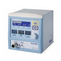
8.2 N6631/LX800 PC Board
1. Disconnect the display cable (A).
2. Remove the screws (B) and washers (C)
that retain the PC board to the support pillars.
3. Disconnect the inverter enable cable (D)
and the PC board power connector (E).
4. Gently disconnect the PC board (F) from
the CAN card by lifting the board vertically,
until all the connector pins are disengaged
from the socket.
5. Disconnect the interface cables (G) from the
PC board.
6. Disconnect the serial controller cable (H)
from the PC board.
7. The PCB spacers (I) are now loose.
8. Assembly is the reverse of removal.
Setup: Confirm that the ventilators time and date settings are correct. (Refer to the user
manual for more details on how to set the time and date).
B
B
B
B
C
C
C
D
G
G
E
F
A
H
I
I
I