Page 38 (Model J)
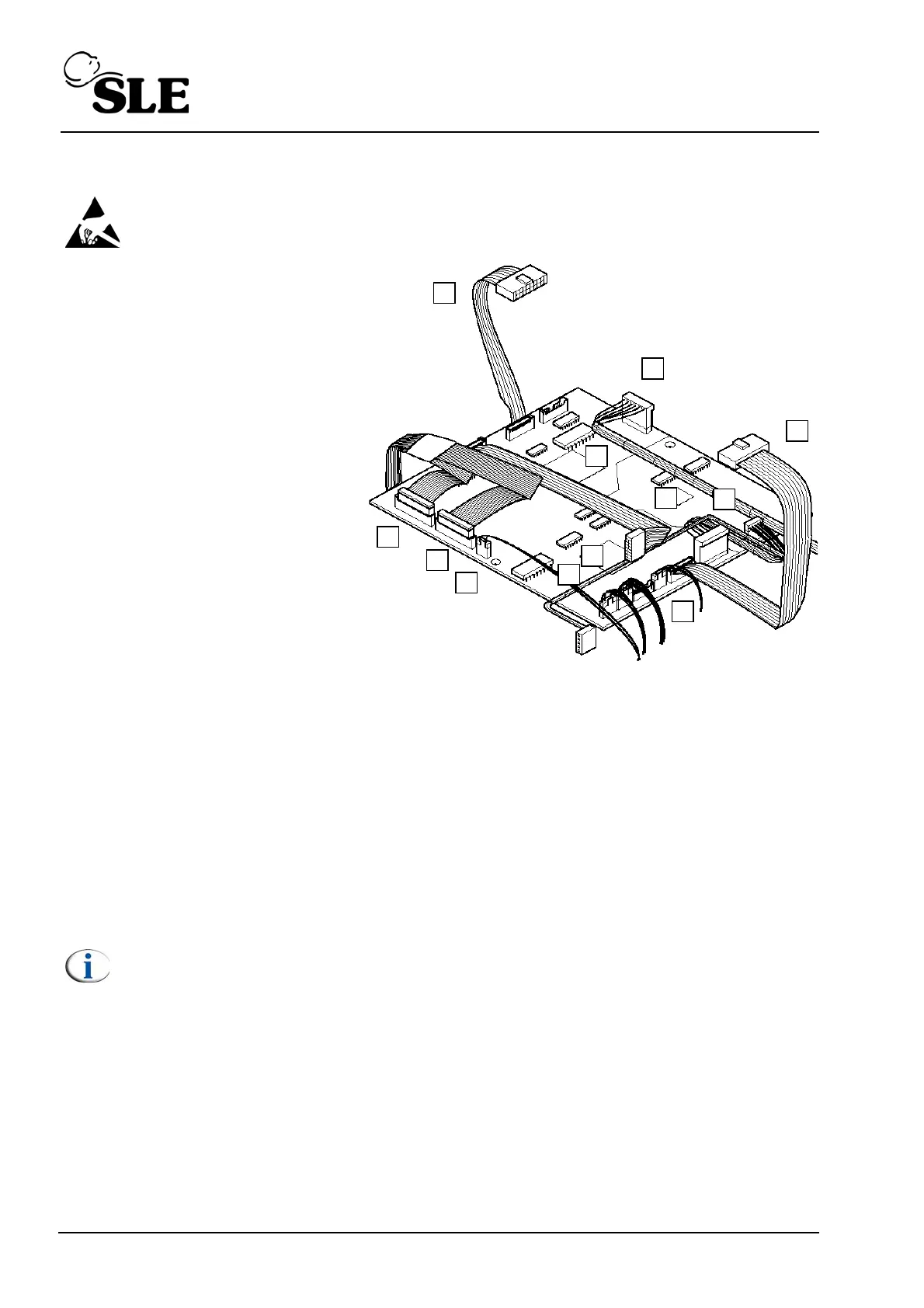
8.6 A0763/02/M Control/Monitor Board
Warning: The Control/Monitor Board is a static sensitive device.
1. Remove the L0275/OEM2
Computer/Display Control
assembly as described in section
8.5.
2. Disconnect the following cables.
3. CAN card link ribbon cable
controller side (A). (P3)
4.CAN card link ribbon cable
controller side (B). (JP3)
5. Power supply connector
controller side, main loom (C). (P4)
6. Controller to A0761 transducer
assembly ribbon cable (D). (P5)
7. Conventional valve drive ribbon
cable (E). (P6)
8. Analogue valve drive ribbon
cable (F). (P7)
9. Alarm sounder cable, main loom (G). (JP5)
10. Battery/power supply sensing connector, main loom (H). (JP9)
11. Controller to A0761 transducer assembly connector (I). (JP7)
12. O
2
cell connector (J). (JP8)
13. Power supply connector monitor side, main loom (K). (JP6)
14. Flow sensor connector (L). (JP4)
15. The control and monitor board can now be removed.
Note: For a detailed description. Refer to “A0763/02/M Monitor and control
board” on page 56.
16. Assembly is the reversal of removal.
Setup: A full system calibration is required for this component.
E
F
H
I
J
K
B
C
A
D
G
L