Page 42 (Model J)
8.10 N6631/13 Inverter PCB
Warning: The Transducer PCB is a static sensitive device.
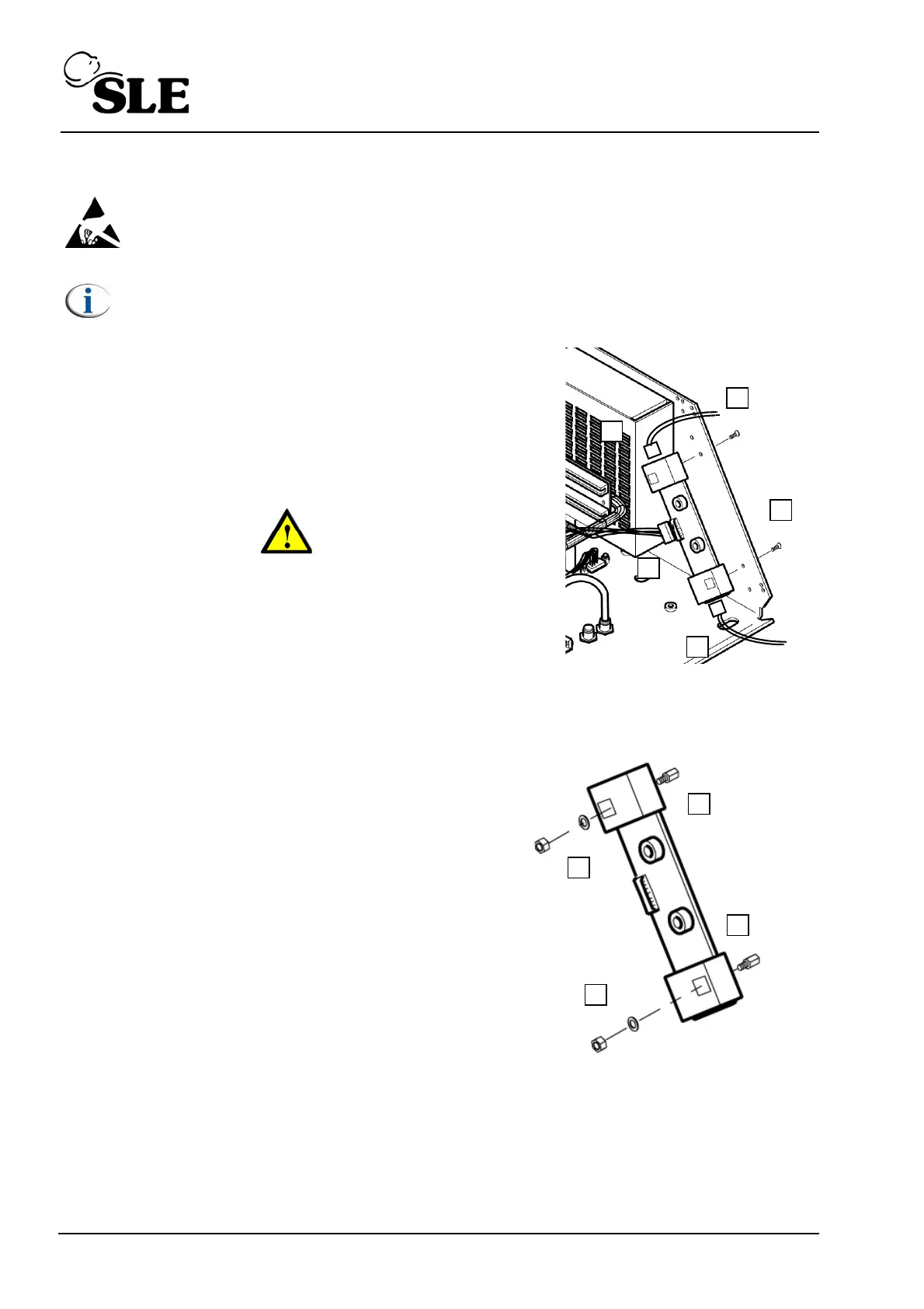
Note: Screen removed for clarity.
1. Remove the L0275/OEM2 Computer/Display Control
assembly as described in section 8.5.
2. Remove the Control/Monitor board as described in
section 8.6.
3. Remove the two screws (A).
Warning: The PCB is still attached by the backlight
connectors to the LCD / Touch screen assembly.
4. Disconnect the two backlight connectors (B).
5. Disconnect the Inverter/L0275/OEM2 connector cable
(C).
6. Remove the PCB from the electronic unit.
7. Remove the two support pillars (D) by removing
the nut and washers (E).
8. Assembly is reversal of removal.
Setup: No setup is required for this device.