(Model J) Page 43
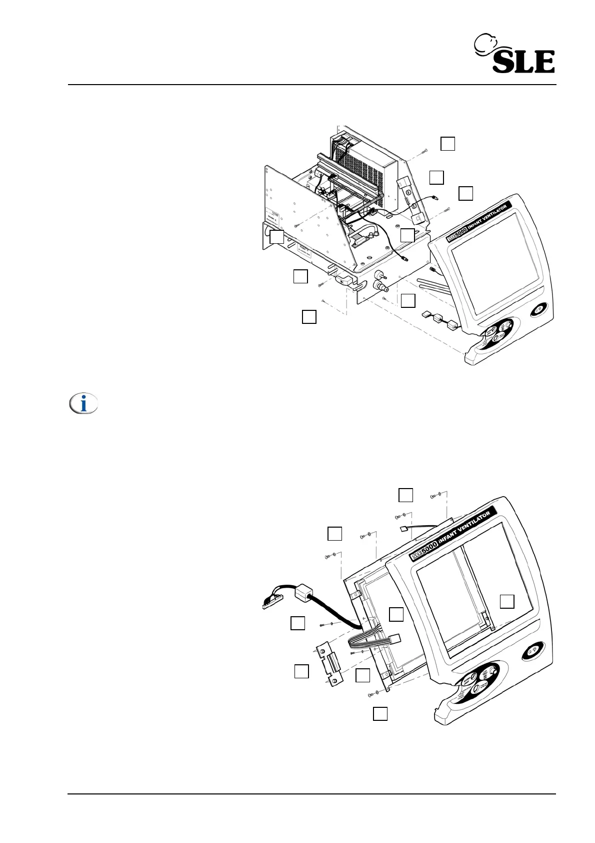
8.11 N6631/02 LCD & N6631/05 Touch Screen
1. Remove the L0275/OEM2
Computer/Display Control
assembly as described in section
8.5.
2. Remove the Control / Monitor
board as described in section 8.6.
3. Remove the 4 screws (A)
retaining the screen tie bars.
4. Remove the 3 remaining facia
retaining screws (B).
5. Gently draw the front panel
assembly away from the unit.
6. Disconnect the two backlight
power leads from the inverter
board (See section 8.10 on page
42).
Note: Display / touch screen cables not shown for clarity.
7. Disconnect the two tubes (C).
8. Disconnect the fan electrical connector (D).
9. Disconnect the led electrical connector (E).
10. Remove the 6 facia retaining
screws and washers (F).
11. Remove the front facia.
12. Withdraw the touch screen
cable (G) through the hole in the
LCD cable clamp plate (I).
13. Remove the two screws and
washers (H) retaining the LCD
cable clamp plate (I).
14. Slide out the LCD retaining
clamp (I).
15. Remove the 2 screws (J)
retaining the right hand side of the
LCD / touch screen assembly.