(Model J) Page 41
8.9 A0761 Transducer PCB Assembly
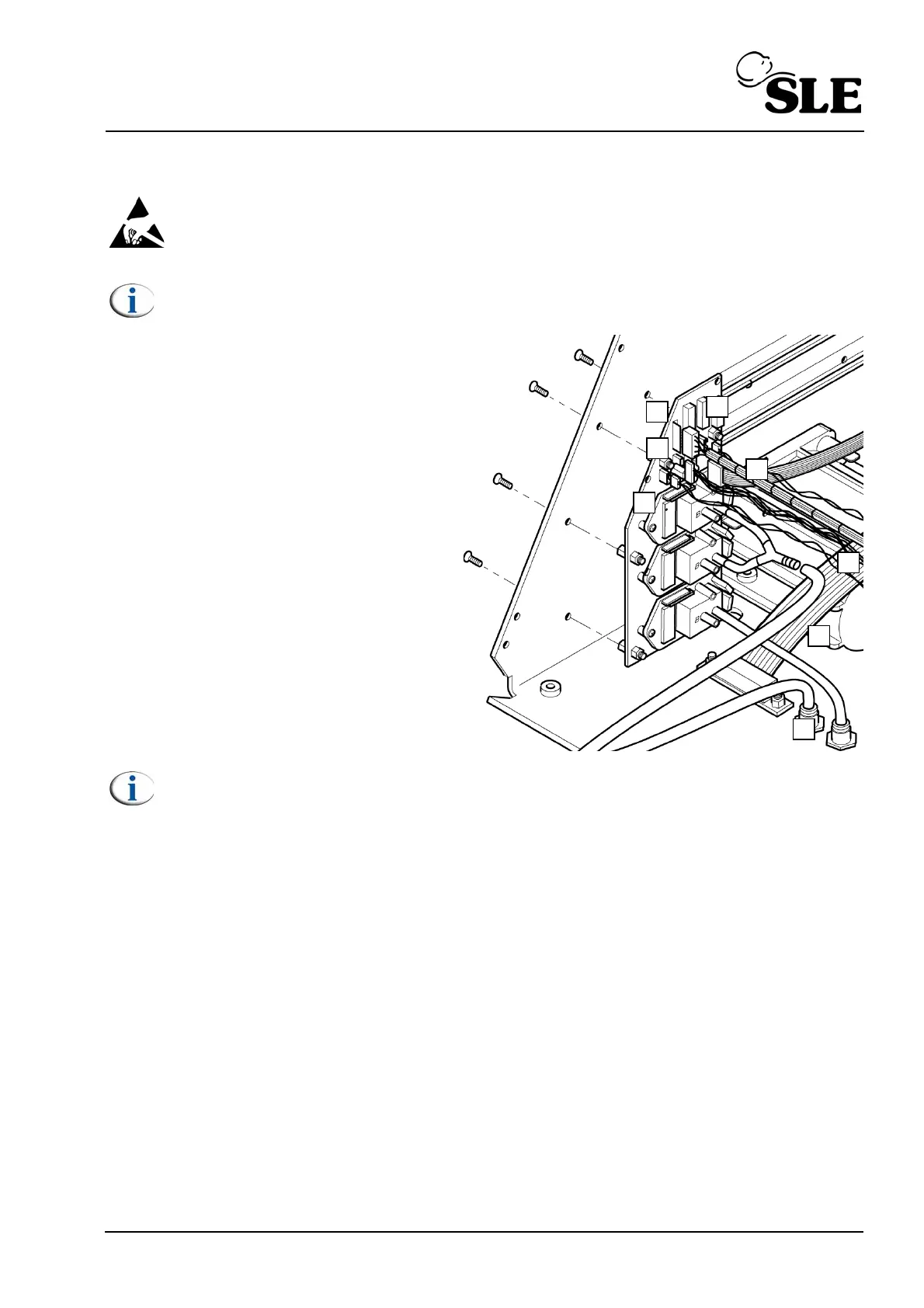
Warning: The Transducer PCB is a static sensitive device.
Note: Screen removed for clarity.
1. Remove the L0275/OEM2 Computer/
Display Control assembly as described in
section 8.5.
2. Remove the Control/Monitor board as
described in section 8.6.
3. Disconnect the ribbon cable from J2
(A).
4. Disconnect the main loom connector
from J5 (B).
5. Disconnect the LED connector from J4
(C).
6. Disconnect the loom connector from J3
(D).
7. Disconnect the loom connector from J1
(E).
Note: The tubes connected to the transducer PCB are attached using an
adhesive.
8. Remove the tube (F) from the Y piece connector.
9. Remove the tube (G) from the bulk head connector (H).
10. Remove the six fixing screws retaining the transducer PCB.
11. Assembly is reversal of removal.
Setup: A full system calibration is required for this component.