133
Electrical Connection
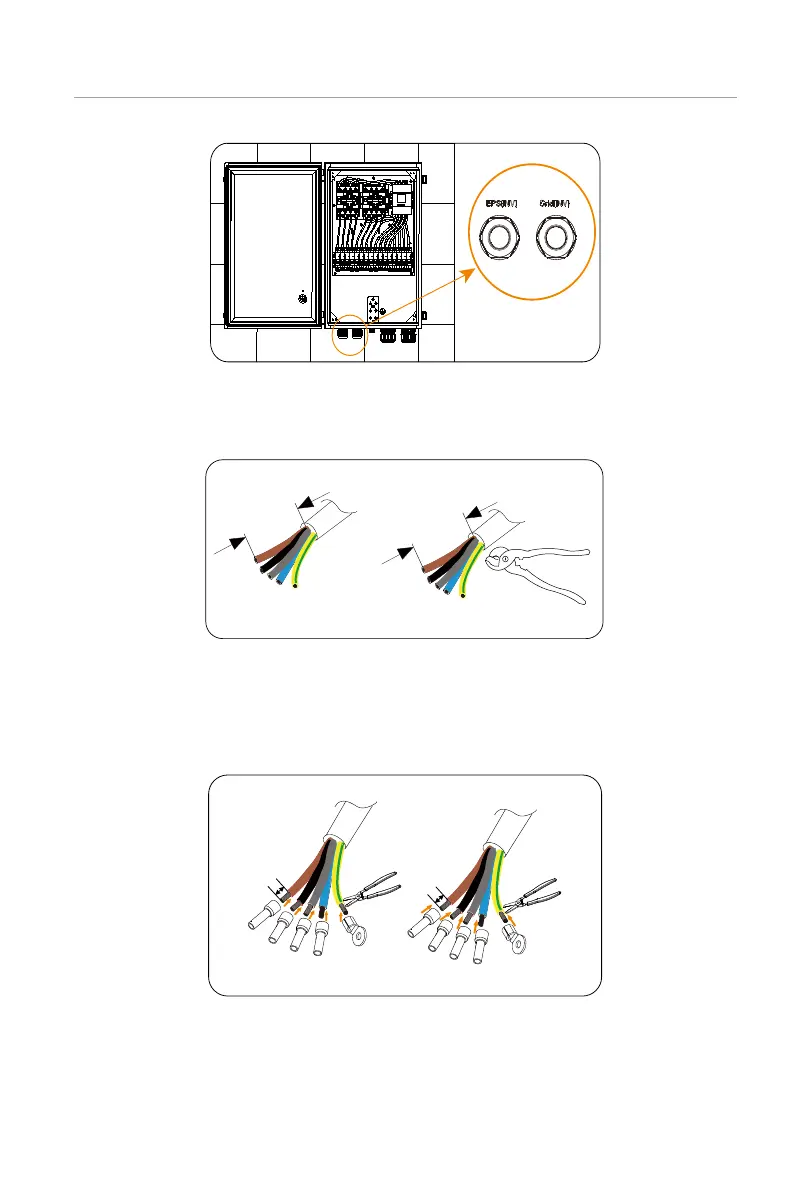
Figure 7-77 Confirming the ports
Step 4: Prepare two 10 mm² five-core cable. Strip 200 mm outer insulation jacket off the
EPS (INV) and Grid (INV) cable with a wire cutter.
200 mm
10 mm²
Grid (INV)
EPS (INV)
Five-core cable Five-core cable
200 mm
10 mm²
Figure 7-78 Stripping the EPS (INV) and Grid (INV)cable
Step 5: Strip 12 mm insulation jacket off L1, L2, L3, N and PE cables of the EPS (INV) and
Grid (INV) cable with a wire stripper. Insert 10 mm² ferrules into the L1, L2, L3 and
N cables of the EPS (INV) and Grid (INV) cable and 10 mm² OT terminal into the
PE cable.
12 mm
10 mm²
ferrules
10 mm² OT
terminals
12 mm
10 mm²
ferrules
10 mm² OT
terminals
Grid (INV)
EPS (INV)
Figure 7-79 Stripping cables and inserting terminals into cables
Step 6: Crimp L1, L2, L3 and N cable of the EPS (INV) and Grid (INV) cable with a crimping
tool for ferrules. And crimp the PE cable of the two cables with a crimping tool.

 Loading...


