137
Electrical Connection
200 mm
200 mm
Grid
Load
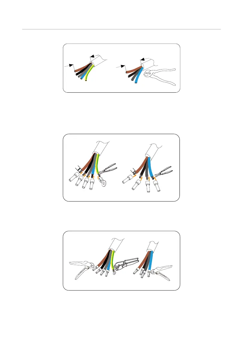
Figure 7-89 Stripping the Grid and Load cable
Step 14: Strip 12 mm insulation L1, L2, L3, N and PE cable of the Grid cable and strip 12
mm insulation L1, L2, L3, N cable of the Load cable. Insert 14 mm² ferrules into L1,
L2, L3 and N cable of the Grid and Load cable. Insert the 14 mm² OT terminal into
the PE cable of the Grid cable.
12 mm
12 mm
14 mm² ferrules
14 mm² OT
terminals
14 mm² ferrules
Grid
Load
Figure 7-90 Assembling the Grid annd Load cable
Step 15: Crimp the L1, L2, L3 and N cable of the Grid and Load cable with a crimping tool
for ferrules. And crimp the PE cable of the Grid cable with a crimping tool.
Figure 7-91 Crimping terminals
Step 16: Anti-clockwise the swivel nuts of the Grid and Load port.

 Loading...


