168
Operation on LCD
Setting Meter/CT Settings
You need to select the CT or electricity meter to connect the inverter. CT is set by default.
NOTICE!
• If the user has other power generation equipment (such as inverter) at home and
wants to monitor both, the inverter provides Meter2 communication function
to monitor the power generation equipment. Please refer to section “Meter/CT
Connection (Meter/CT Port)” for specific meter connection diagram.
• Generally, the address and direction of the meter do not need to be set, reset them if
you want to change them.
a. Select the Meter/CT Setting in the Adcance Settings interface and enter the
interface.
b. Set the Meter/CT:
»
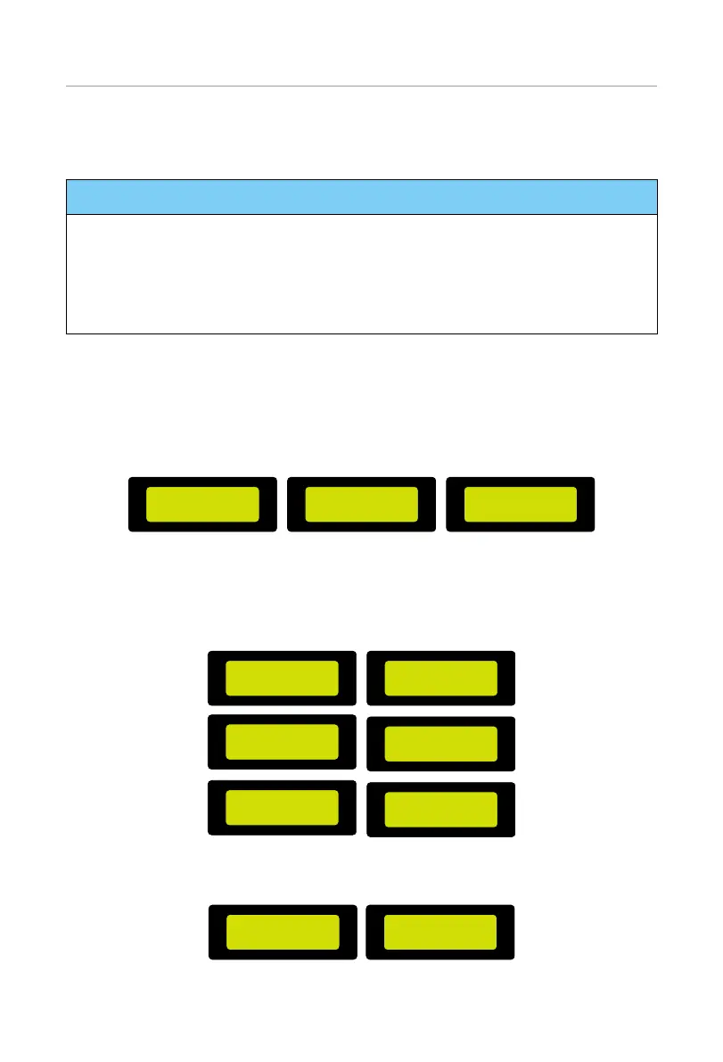
Case 1: CT and Meter 2 are connected. (CT for SolaX inverter, Meter 2
for another power generation equipment) CT is set by default. Check the
address and direction of Meter2 are set based on actual connection.
==Meter/CT Setting==
Select
> CT <
==Meter/CT Setting==
Meter2Addr:
2
==Meter/CT Setting==
Meter2 Direction:
> Positive <
Figure 9-48 Selecting CT and set Meter2 data
»
Case 2: Meter 1 and Meter 2 are connected. (Meter 1 for SolaX inverter, Meter
2 for another power generation equipment). Select Meter and enble the
Meter function. Check the address and direction of Meter1 and Meter2 are
set based on actual connection.
==Meter/CT Setting==
Select
> Meter <
==Meter/CT Setting==
Select:
> Enable <
==Meter/CT Setting==
Meter1Addr:
1
==Meter/CT Setting==
Meter2Addr:
2
==Meter/CT Setting==
Meter1 Direction:
> Positive <
==Meter/CT Setting==
Meter2 Direction:
> Positive <
Figure 9-49 Selecting meter and set Meter1 and Meter2 data
c. Set the CT type: select 100A or 200A CT.
==Meter/CT Setting==
CT Type
100A
==Meter/CT Setting==
External INV
> Disable <
Figure 9-50 Setting the limits

 Loading...