62
Mechanical Installation
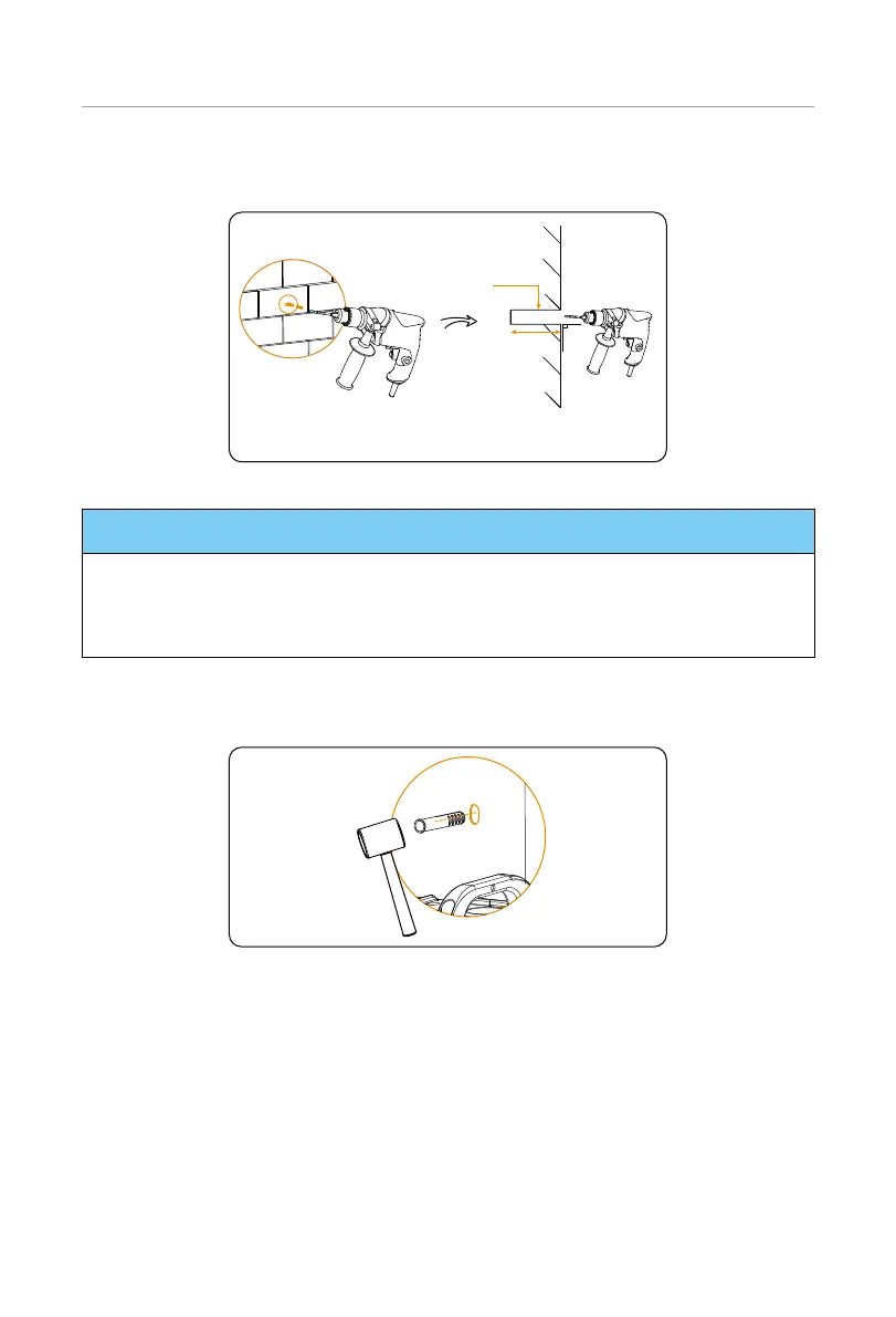
Step 7: Remove the assembled bracket, and then drill two holes at a depth of more than
60 mm in the concrete wall by using a drill (Ø10 mm).
Concrete Wall
90°
Ø10 mm Drill
> 60 mm
Figure 6-9 Drilling holes
NOTICE!
• An electric drill dust collector is recommended.
• To prevent dust from being released into the hot plug when drilling holes, users
may use the package bag of the device or other materials to fully cover the battery
module.
Step 8: Insert the expansion bolts into two holes, tighten the tapping screws to secure
the assembled bracket on the wall (torque: 8-10 N·m), and then tighten M5*14
screws on both sides (torque: 2.2-2.5 N·m).
Figure 6-10 Inserting the expansion bolt

 Loading...


