64
Mechanical Installation
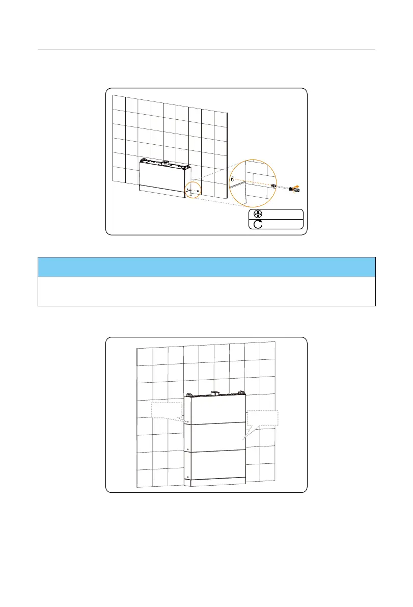
Step 10: Insert and tighten M5*14 screws on both sides (torque: 2.2-2.5 N·m).
M5*14
2.2-2.5 N·m
Figure 6-13 Tightening screws
NOTICE!
• Please make sure that the corners and edges of the base and battery module are
aligned before tightening screws.
Step 11: Place the second and third battery modules, and make sure that the corners and
edges of the battery modules are aligned.
Step 9
Steps 9
to 10
Figure 6-14 Placing battery modules
Step 12: Locate the position of the BMS and the inverter.
1. Attach the angle bracket and adjustable bracket together, tighten but not lock
them with a M5*14 screw for a while;
2. Align the bracket with the holes on the BMS. Mark four dots through the

 Loading...


