5-4
5-1. CAMERA SECTION ADJUSTMENT
1-1. PREPARATIONS BEFORE ADJUSTMENT (CAMERA SECTION)
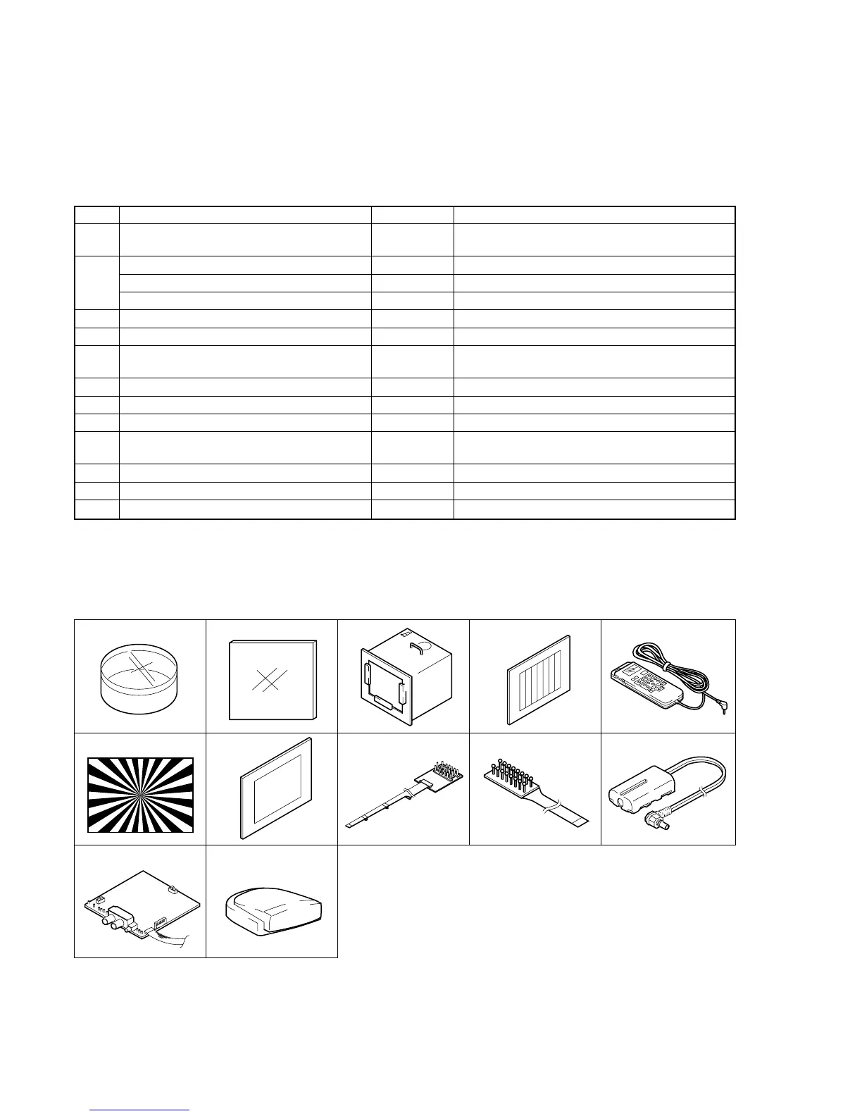
1-1-1. List of Service Tools
• Oscilloscope • Color monitor • Vectorscope
• Regulated power supply • Digital voltmeter
Note1: If the micro processor IC in the adjustment remote commander is
not the new micro processor (UPD7503G-C56-12), the pages
cannot be switched. In this case, replace with the new micro
processor (8-759-148-35).
Note2: Connect the adjustment remote commander to the LANC jack,
and set to HOLD switch to the “ADJ” side.
Ref. No.
J-1
J-2
J-3
J-4
J-5
J-6
J-7
J-8
J-9
J-10
J-11
J-12
Name
Filter for color temperature correction (C14)
ND filter 1.0
ND filter 0.4
ND filter 0.1
Pattern box PTB-450
Color chart for pattern box
Adjustment remote commander (RM-95 upgraded)
(Note1)
Siemens star chart
Clear chart for pattern box
Multi CPC jig
CPC-7 jig
Power code (Note2)
AFM DEV jig
IR receiver jig
Parts Code
J-6080-058-A
J-6080-808-A
J-6080-806-A
J-6080-807-A
J-6082-200-A
J-6020-250-A
J-6082-053-B
J-6080-875-A
J-6080-621-A
J-6082-311-A
J-6082-382-A
J-6082-223-A
J-6082-312-A
J-6082-383-A
Usage
Auto white balance adjustment/check
White balance adjustment/check
White balance check
White balance check
White balance check
For checking the flange back
For adjusting the LCD block
For adjusting the video section
For adjusting the color viewfinder
For connecting the battery terminal and DC power supply
For adjusting the deviation
For adjusting the IR transmitter
J-1 J-2
J-6
J-3
J-7 J-8
J-4 J-5
Fig. 5-1-1.
J-9 J-10
J-11 J-12