5-8
1-1-3. Precaution
1. Setting the Switch
Unless otherwise specified, set the switches as follows and perform
adjustments without loading cassette.
1. POWER switch (MA-374/375 board).................... CAMERA
2. NIGHT SHOT switch (Lens block) .................................OFF
3. VIDEO LIGHT switch (MA-374/375 board) (Note1).....OFF
4. DEMO MODE (Menu display) .......................................OFF
5. DIGITAL ZOOM (Menu display) ...................................OFF
6. STEADY SHOT (Menu display) (Note2)........................OFF
7. DISPLAY (Menu display) (Note3) .................... V-OUT/LCD
8. DISPLAY (CF-66/67 board) (Note3) ............................... ON
9. FOCUS switch (MR-8500 block) ......................... MANUAL
10. PROGRAM AE (CF-66/67 board) .................................. Auto
11. BACK LIGHT (CF-66/67 board).....................................OFF
12. PICTURE EFFECT (CF-66/67 board) ............................OFF
13. DIGITAL EFFECT (CF-66/67 board) (Note4) ................OFF
14. 16 : 9 WIDE (MENU display) .........................................OFF
Note1: VIDEO LIGHT model (CCD-TRV17/TRV37/TRV57/TRV57P/TRV67/TRV87/TRV87P) only.
Note2: STEADY SHOT model (CCD-TRV57/TRV57P/TRV67/TRV87/TRV87P) only.
Note3: TRV model (CCD-TRV17/TRV37/TRV47/TRV57/TRV57P/TRV67/TRV87/TRV87P) only.
Note4: DIGITAL EFFECT model (CCD-TRV87/TRV87P) only.
2. Order of Adjustments
Basically carry out adjustments in the order given.
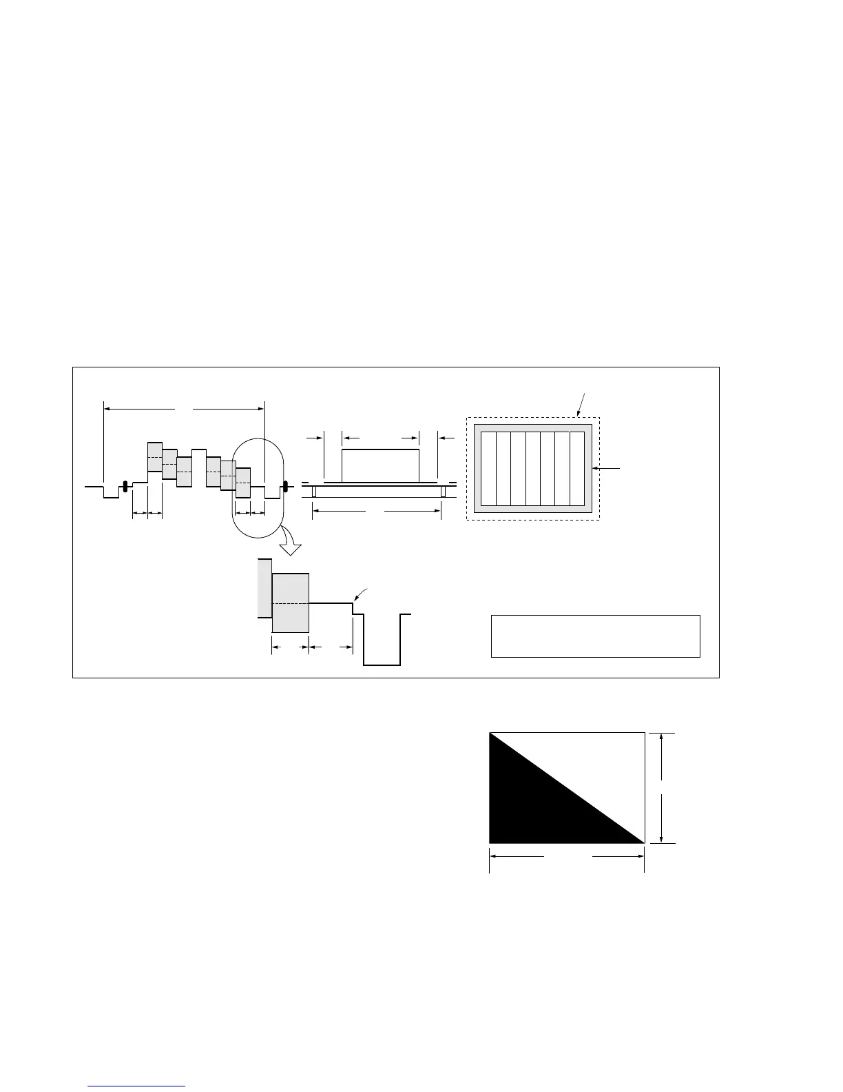
Fig.5-1-5.
3. Subjects
1) Color bar chart (Color reproduction adjustment frame)
When performing adjustments using the color bar chart, adjust
the picture frame as shown in Fig. 5-1-5. (Color reproduction
adjustment frame)
2) Clear chart (Color reproduction adjustment frame)
Remove the color bar chart from the pattern box and insert a
clear chart in its place. (Do not perform zoom operations during
this time.)
3) Flange back adjustment chart
Make the chart shown in Fig. 5-1-6 using A0 size (1189mm ×
841mm) black and white vellum paper.
Fig. 5-1-6.
Note: Use matte vellum paper bigger than A0, and make sure the edges of
the black and white paper joined together are not rough.
H
A=B
C=D
AB B
CD
A
Enlargement
V
Electronic beam scanning frame
CRT picture frame
B
A
Difference in level
Yellow
Cyan
Green
White
Magenta
Red
Blue
Yellow
Cyan
Green
White
Magenta
Red
Blue
Color bar chart (Color reproduction adjustment frame)
Fig. a
(VIDEO terminal
output waveform)
Fig. b (monitor TV picture)
Adjust the camera zoom and direction to
obtain the output waveform shown in Fig. a
and the monitor TV display shown in Fig. b.
White
Black
841m