5-25
8. Auto White Balance Adjustment
Adjust to the proper auto white balance output data.
If it is not correct, auto white balance and color reproducibility will
be poor.
Subject Clear chart
(Color reproduction adjustment frame)
Filter Filter C14 for color temperature
correction
Measurement Point Display data of page 1 (Note2)
Measuring Instrument Adjustment remote commander
Adjustment Page F
Adjustment Address 42, 43
Specified Value 760H model:
R ratio: 2BC0 to 2C40
B ratio: 6060 to 6120
510H TYPE P model:
R ratio: 2A40 to 2AC0
B ratio: 5E20 to 5EE0
510H TYPE S model:
R ratio: 2B60 to 2BE0
B ratio: 5EA0 to 5F60
Note1: Perform “Auto White Balance & LV Standard Data Input” before
this adjustment.
Note2: Displayed data of page 1 of the adjustment remote commander.
1 : XX : XX
Display data
Note3: 760H model:
CCD-TRV87/TRV87P
510H TYPE P model:
CCD-TRV57/TRV57P/TRV67
510H TYPE S model:
CCD-TR317/TR517/TRV17/TRV37/TRV47
Switch setting:
1) NIGHT SHOT ..................................................................OFF
2) DIGITAL ZOOM (Menu display) ...................................OFF
3) STEADY SHOT (Menu display) .....................................OFF
4) VIDEO LIGHT ................................................................OFF
Adjusting method:
1) Place the C14 filter for color temperature correction on the
lens.
2) Select page: 0, address: 01, and set data: 01.
3) Select page: F, address: B8 to BB, and note down the data of
each address.
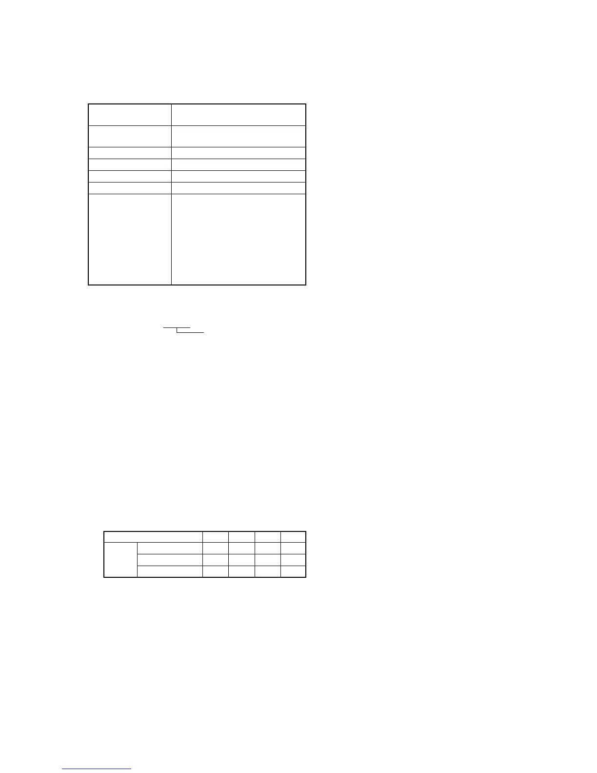
4) Input the following data to page: F, addresses: B8 to BB.
Note: Press the PAUSE button of the adjustment remote commander
each time to set the data.
5) Select page: 6, address: 01, set data: A7, and press the PAUSE
button.
6) Select page: 6, address: 01, set data: A5, and press the PAUSE
button.
(The auto white balance adjustment is performed and the
adjustment data is stored in page: F, address: 42 and 43.)
Address
Data 760H model
510H TYPE P model
510H TYPE S model
B8
2C
2A
2B
B9
00
80
A0
BA
60
5E
5F
BB
C0
80
00
7) Select page: 6, address: 02, and check that the data is “01”.
8) Select page: 6, address: 01, set data: 3F, and press the PAUSE
button.
9) Select page: 0, address: 03, and set data: 04.
10) Select page: 1, and check that the display data (Note2) satisfies
the R ratio specified value.
11) Select page: 0, address: 03, and set data: 05.
12) Select page: 1, and check that the display data (Note2) satisfies
the B ratio specified value.
13) Select page: F, address: B8 to BB, and input the data noted
down at step 3).
Note: After setting each data, be sure to press the PAUSE button of
the adjustment remote commander.
Processing after Completing Adjustments:
1) Select page: 6, address: 01, set data: 00, and press the PAUSE
button.
2) Select page: 0, address: 03, and set data: 00.
3) Select page: 0, address: 01, and set data: 00.