5-44
3-4. VIDEO SYSTEM ADJUSTMENTS
Video system adjustments must be performed in the following order.
[Adjusting Order]
1. 28MHz origin oscillation adjustment
2. AFC f
0
adjustment
3. Filter f
0
adjustment
4. Y OUT level adjustment
5. C OUT level adjustment
6. REC Y current adjustment
7. REC C/AFM Current Adjustment
1. 28 MHz Origin Oscillation Adjustment (VC-234 board)
Set the frequency of the clock for synchronization.
If deviated, the synchronization will be disrupted and the color will
become inconsistent.
Mode VTR stop
Signal No signal
Measurement Point Pin ia of IC201 or pin qs of IC501
Measuring Instrument Frequency counter
Adjustment Pag F
Adjustment Address 4D
Specified Value f=14318181 ± 68Hz
Adjusting method:
1) Select page: 0, address: 01, and set data: 01.
2) Select page: 2, address: 01, set data: 41, and press the PAUSE
button of the adjustment remote commander.
3) Select page: 6, address: 61, and set data: 30.
4) Select page: F, address: 4D, change the data and set the clock
frequency (f) to the specified value.
5) Press the PAUSE button of the adjustment remote commander.
6) Select page: 6, address: 61, and set data: 10.
7) Select page: 2, address: 01, set data: 00, and press the PAUSE
button of the adjustment remote commander.
8) Select page: 0, address: 01, and set data: 00.
2. AFC f
0
Adjustment (VC-234 board)
Adjust the pull-in range of the A/D converted clock generator during
playback.
Mode VTR stop
Signal No signal
Measurement Point Display data of page: 6, address: 02
Measuring Instrument Adjustment remote commander
Adjustment Page F
Adjustment Address 65
Specified Value 01
Adjusting method:
1) Select page: 0, address: 01, and set data: 01.
2) Select page: 2, address: 01, set data: 4D, and press the PAUSE
button of the adjustment remote commander.
3) Select page: 6, address: 01, set data: C5, and press the PAUSE
button.
(The AFC fo adjustment is performed and the adjustment data
is stored in page: F, address: 65.)
4) Select page: 6, address: 02, and check that the data is “01”.
5) Select page: 6, address: 01, set data: 00, and press the PAUSE
button.
6) Select page: 2, address: 01, set data: 00, and press the PAUSE
button.
7) Select page: 0, address: 01, and set data: 00.
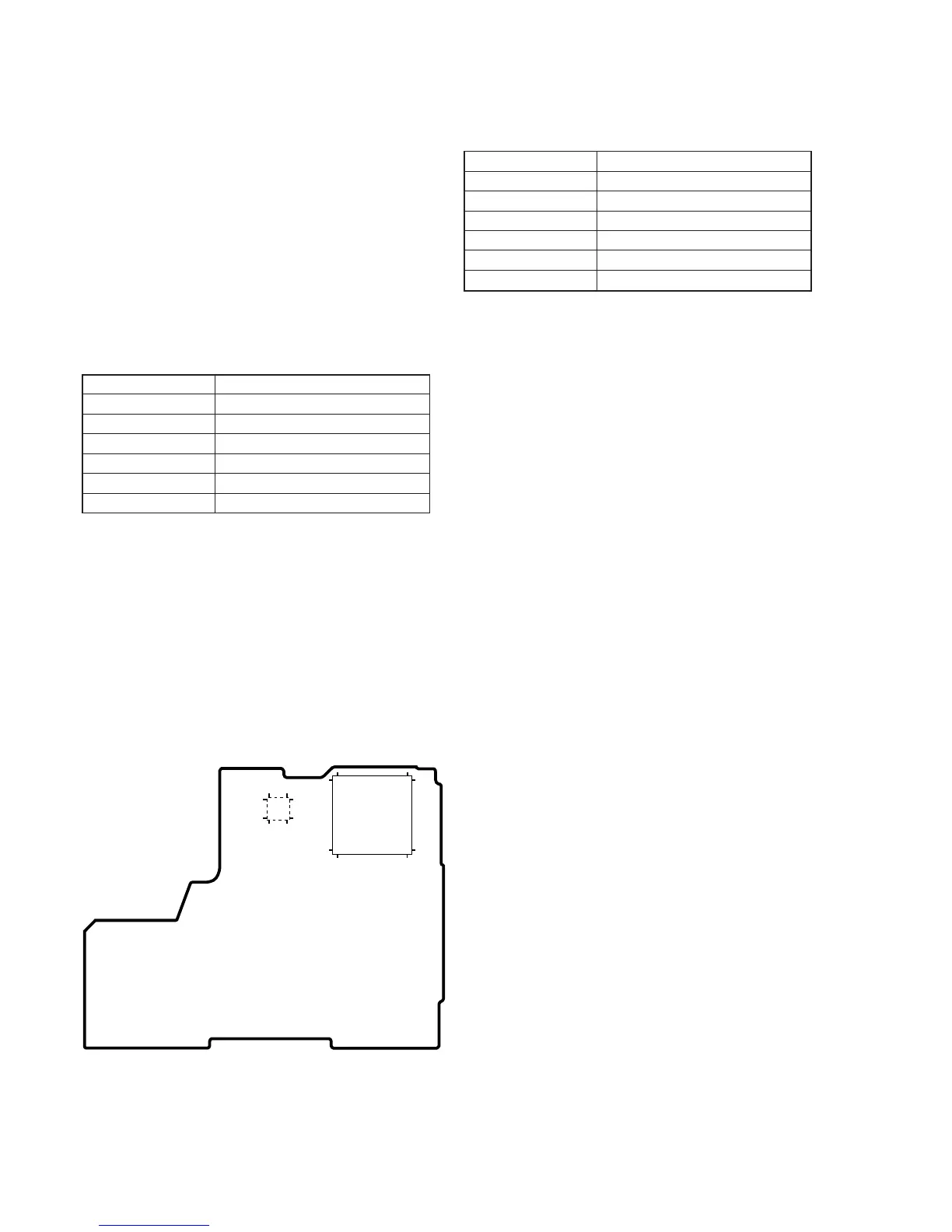
IC501
1324
4837
36 1
25 12
IC201
541
163
108
162 109
216 55
VC-234 BOARD
Fig. 5-3-6.