5-36
4. Contrast Adjustment (PD-117 board)
Set the level of the VIDEO signal for driving the LCD to the specified
value. If deviated, the screen image will be blackish or saturated
(whitish).
Mode Camera
Subject Arbitrary
Measurement Point Pin 3 of CN5502 (VG)
External trigger :
Pin 4 of CN5502 (PANEL COM)
Measuring Instrument Oscilloscope
Adjustment Page 7
Adjustment Address ED
Specified Value LCD TYPE S: A = 3.68 ± 0.07V
LCD TYPE C: A = 2.84 ± 0.07V
Note: Refer to “LCD type check” for the discrimination of the LCD type.
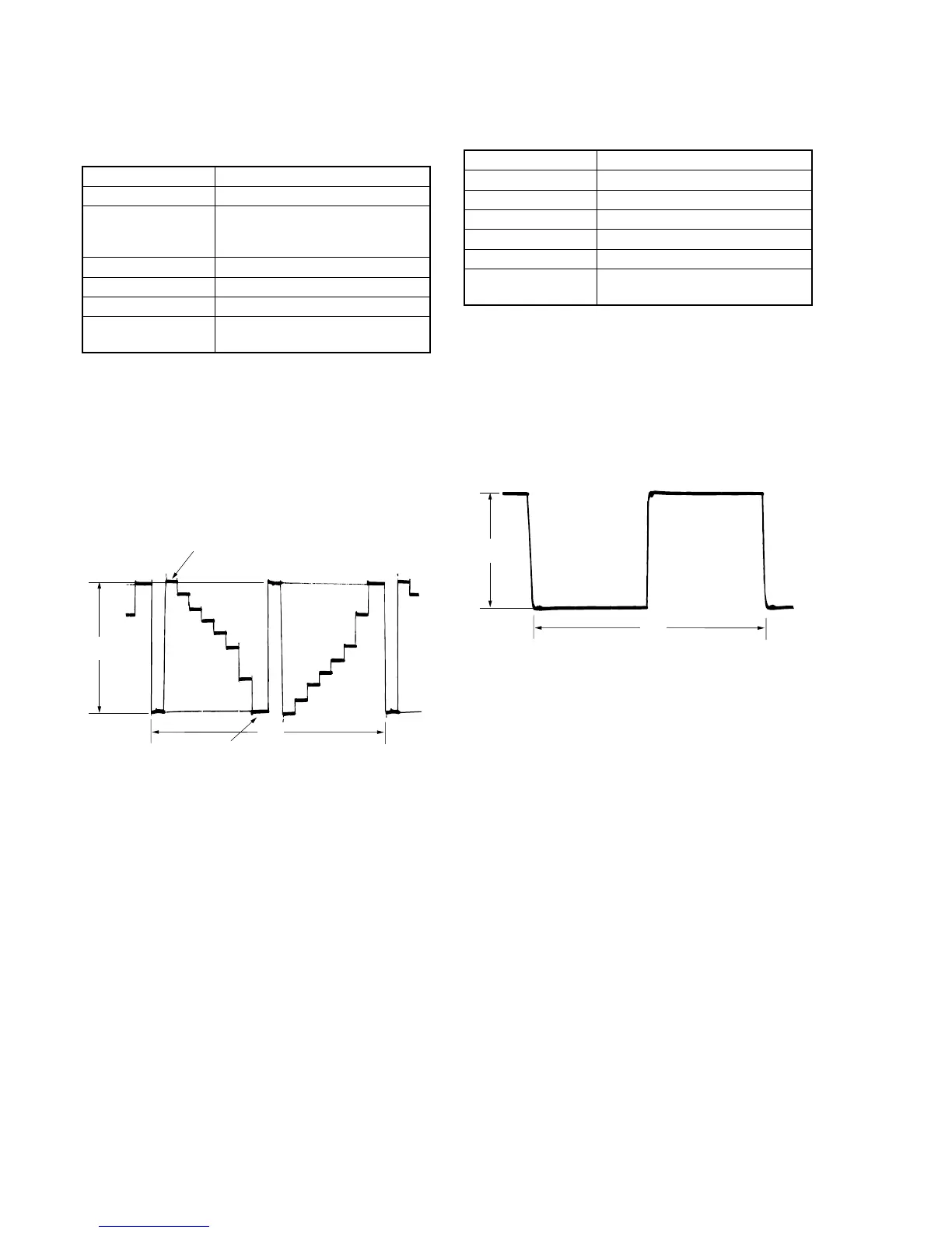
Adjusting method:
1) Select page: 0, address: 01, and set data: 01.
2) Select page: 7, address: ED, change the data and set the voltage
(A) between the pedestal (0 IRE) and 100 IRE to the specified
value.
(The data of address: ED should be “00” to “7F”.)
3) Press the PAUSE button of the adjustment remote commander.
4) Select page: 0, address: 01, and set data: 00.
5. COM AMP Adjustment (PD-117 board)
Set the common electrode drive signal level of LCD to the specified
value.
Mode Camera
Subject Arbitrary
Measurement Point Pin 4 of CN5502 (PANEL COM)
Measuring Instrument Oscilloscope
Adjustment Page 7
Adjustment Address EA
Specified Value LCD TYPE S: A = 6.47 ± 0.05V
LCD TYPE C: A = 5.09 ± 0.05V
Note: Refer to “LCD type check” for the discrimination of the LCD type.
Adjusting method:
1) Select page: 0, address: 01, and set data: 01.
2) Select page: 7, address: EA, change the data and set the PANEL
COM signal level (A) to the specified value.
3) Press the PAUSE button of the adjustment remote commander.
4) Select page: 0, address: 01, and set data: 00.
Fig. 5-1-23.
Fig. 5-1-24.
100 IRE
Pedestal
A
2H
A
2H