2-10
2-9. DD-134, SE-101 BOARDS
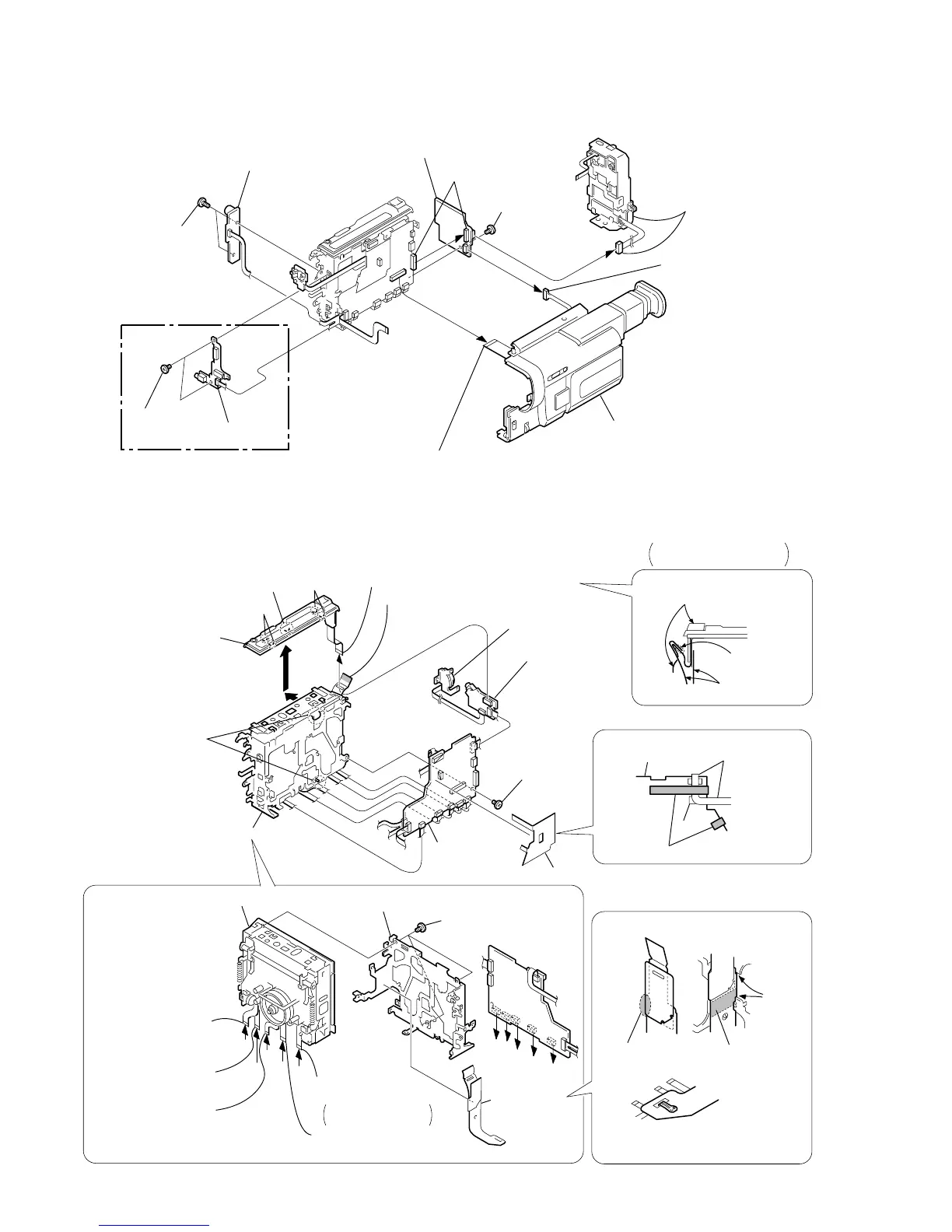
2-10.VC-234, EJ-29/30 BOARDS, MECHANISM DECK-2
VC-234
Board
DD-134
6
Board to board
connector (48P)
7
DD-134 board
9
PJ-99 board (TR model)
PJ-100 board (TRV model)
qa
SE-101
board
8
Two screws
(M2
×
4),
lock ace, p2
5
Screw
(M2
×
3)
q;
Two screws
(M2
×
3)
4
Battery panel
block assembly
(7P)
2
DP-78 harness (8P
(TRV model)
1
FFC-001 flexible flat cable (45P)
3
Cabinet (R) block assembly
(TRV MODEL)
Board
VC-234
VC-234
Board
D
E
F
G
H
D
E
F
G
H
1
Claw
3
Peel off the area
shown by shading.
B
B
7
Screw
(M2
×
3)
6
Three screws
(M2
×
3)
8
MD frame (A)
7
LS flexible
protector (97)
Notchs
Folding here
5
FP-220
flexible board (8P)
from loading motor,
mode switch
1
FP-221
flexible board (15P)
(from S/T reel sensor)
2
Flexible board (12P)
(from capstan motor)
3
Flexible board (10P)
(from drum motor)
4
Flexible board (16P)
(from video head)
(Long)
(Short)
IC
9
IM guard sheet (97)
IM guard sheet (97)
8
Two claws
q;
VC-234
board
VC-234 board
qa
9
Mechanism deck
2
Slide it in the direction
of the arrow
A
and
disengage the claws
B
Remove the control switch
block(FK-8500) in the
direction of the arrow
C
.
4
Control switch block (FK-8500) (10P)
Control switch block
(FK-8500)
6
Control switch block
(SS-9700)
LS flexible
protector (97)
Adhering
Adhering
5
EJ-29 board
(TR model)
EJ-30 board
(TRV model)
C
A
FP-46 flexible board
(Video light model)
PRECAUTION DURING
INSTALLATION
REMOVING THE
MECHANISM DECK
(PRECAUTION DURING INSTALLATION)
(PRECAUTION DURING INSTALLATION)