5-45
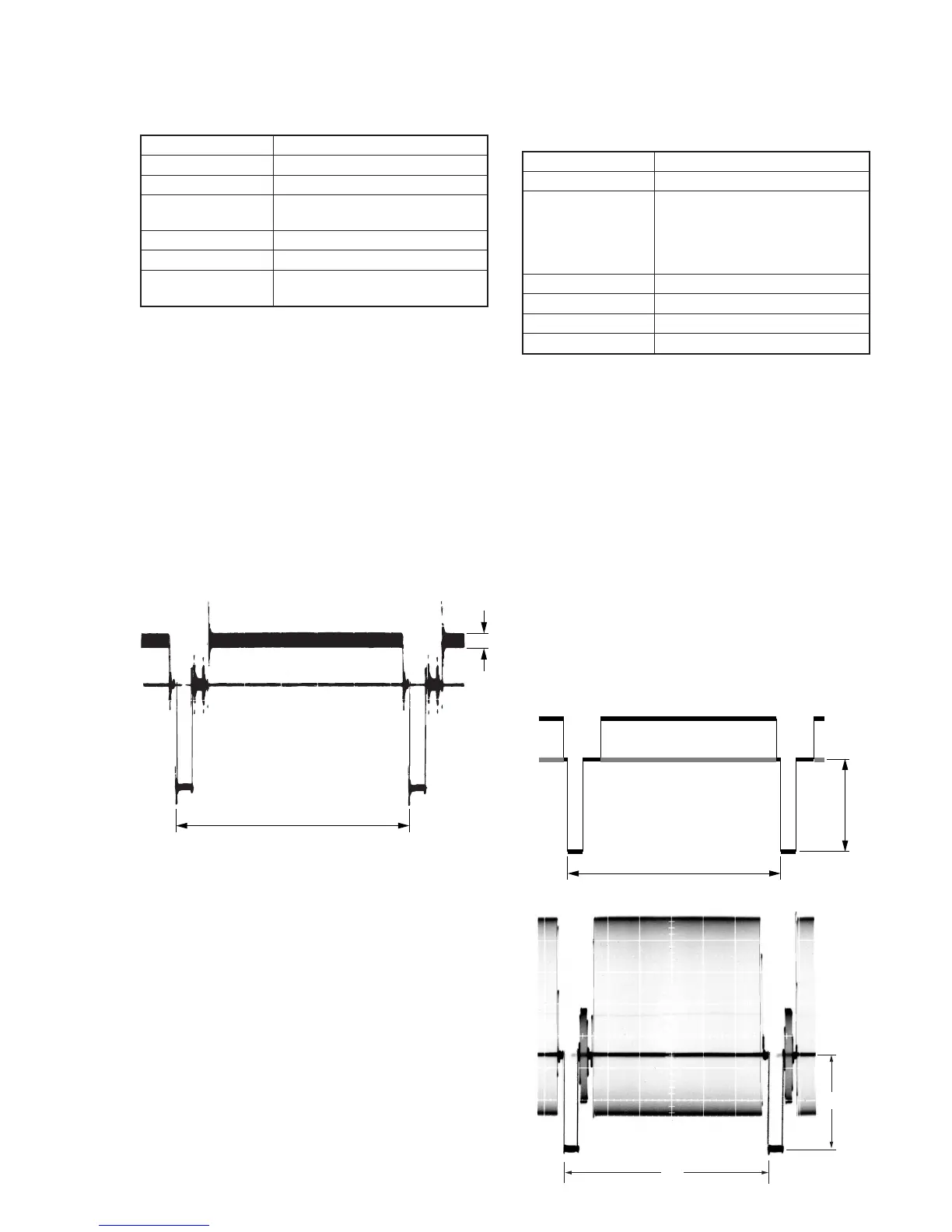
3. Filter f
0
Adjustment (VC-234 board)
Adjust the f
0
frequency of the IC641 built-in filter.
Mode VTR stop
Signal No signal
Measurement Point Pin 3 of CN982 (IR VIDEO)
Measuring Instrument Oscilloscope
(20 MHz BW LIMIT: ON)
Adjustment Page F
Adjustment Address 66
Specified Value Minimum residual chroma signal
components
Adjusting method:
1) Select page: 0, address: 01, and set data: 01.
2) Select page: 2, address: 01, set data: 4F, and press the PAUSE
button of the adjustment remote commander.
3) Select page: 2, address: 05, and set data: 40.
4) Select page: F, address: 66, change the data and minimize the
residual chroma signal components (A).
(The data of address: 66 should be “70” to “7F”.)
5) Press the PAUSE button of the adjustment remote commander.
6) Select page: 2, address: 01, set data: 00, and press the PAUSE
button of the adjustment remote commander.
7) Select page: 2, address: 05, and set data: 00.
8) Select page: 0, address: 01, and set data: 00.
4. Y OUT Level Adjustment (VC-234 board)
Set the Y signal output level. (Adjust the D/A converter out put
level of IC641.)
Mode VTR stop
Signal No signal
Measurement Point Hi8 model:
Y signal terminal of S VIDEO
terminal (75Ω terminated)
Standard8 model:
VIDEO terminal (75Ω terminated)
Measuring Instrument Oscilloscope
Adjustment Page F
Adjustment Address 67
Specified Value A=286 ± 5mV
Note1: Hi8 model:
Insert the plug into the S VIDEO terminal.
Standard8 model:
Insert the plug into the VIDEO terminal.
Note2: Hi8 model:
CCD-TRV67/TRV87/TRV87P
Standard8 model:
CCD-TR317/TR517/TRV17/TRV37/TRV47/TRV57/TRV57P
Adjusting method:
1) Select page: 0, address: 01, and set data: 01.
2) Select page: 2, address: 01, set data: 41, and press the PAUSE
button of the adjustment remote commander.
3) Select page: 6, address: 61, and set data: 30.
4) Select page: F, address: 67, change the data and set the SYNC
level (A) to the specified value.
5) Press the PAUSE button of the adjustment remote commander.
6) Select page: 6, address: 61, and set data: 10.
7) Select page: 2, address: 01, set data: 00, and press the PAUSE
button of the adjustment remote commander.
8) Select page: 0, address: 01, and set data: 00.
H
A
H