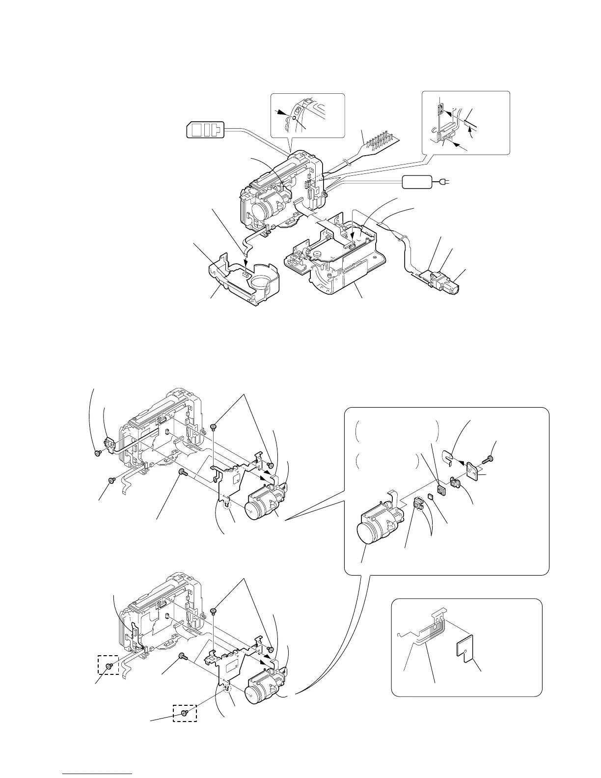
2-9
2-8. LENS DEVICE, CD-239/240 BOARD
MA-
374
AC POWER
ADAPTOR
AC IN
VC-234
Board
CF-66
Board
FP-151 flexible board (20P)
VF-141 board
LB-62 board
Cabinet (R) block assembly
LANC jack
CPC-7 jig
(J-6082-382-A)
CF-66 board
DC IN
CPC-7 jig
Contacting
surface
Front panel block assembly
MA-374 board
FP-43 flexible board
(20P)
Adjustment remote
commander (RM-95)
[VF-141, LB-62, MA-374, CF-66, CD-239 BOARDS SERVICE POSITION]
VF lens (C) (97) assembl
VC-234
Board
VC-234
Board
3
FP-147
flexible board
(14P)
3
FP-147
flexible board (14P)
4
Four claws
6
Optical filter block
7
Shield rubber (FM)
TR317/TR517/TRV17/
TRV37/TRV47/TRV87/
TRV87P
7
Seal rubber (F)
TRV57/TRV57P/
TRV67
5
CCD fitting adaptor (FK)
2
Lens device (LSV-630A)
7
Flexible board
(from Lens block)
(24P)
1
Screw (M2
×
3)
4
Screw (M2
×
3)
6
Claw
9
Lens frame (L)
q;
5
Two screws
(M2
×
3)
2
VL-29
board
8
Two tapping
screws (B2
×
5)
1
Two tapping
screws
(B1.7
×
6)
8
CCD block
assembly
9
CD-239 board
(TR model)
CD-240 board
(TRV model)
REMOVING THE LENS DEVICE,
CD-239/240 BOARD
[ VIDEO LIGHT MODEL ]
1
FP-147
flexible board
(14P)
5
Flexible board
(from Lens block)
(24P)
CD flexible cushion (97)
2
Screw (M2
×
3)
(TRV47 model)
2
Screw (M2
×
3)
(TR317/TR517 model)
4
Claw
7
Lens frame (S)
Lens frame
8
3
Two screws
(M2
×
3)
SE-101 board
(TRV47 model)
6
Two tapping
screws
(B2
×
5)
[ NO VIDEO LIGHT MODEL ]
(PRECAUTION DURING INSTALLATION)