5-37
6. V-COM Adjustment (PD-117 board)
Set the DC bias of the common electrode drive signal of LCD to the
specified value.
If deviated, the LCD display will move, producing flicker and
conspicuous vertical lines.
Mode Camera
Subject Arbitrary
Measurement Point Check on LCD display
Measuring Instrument
Adjustment Page 7
Adjustment Address E7
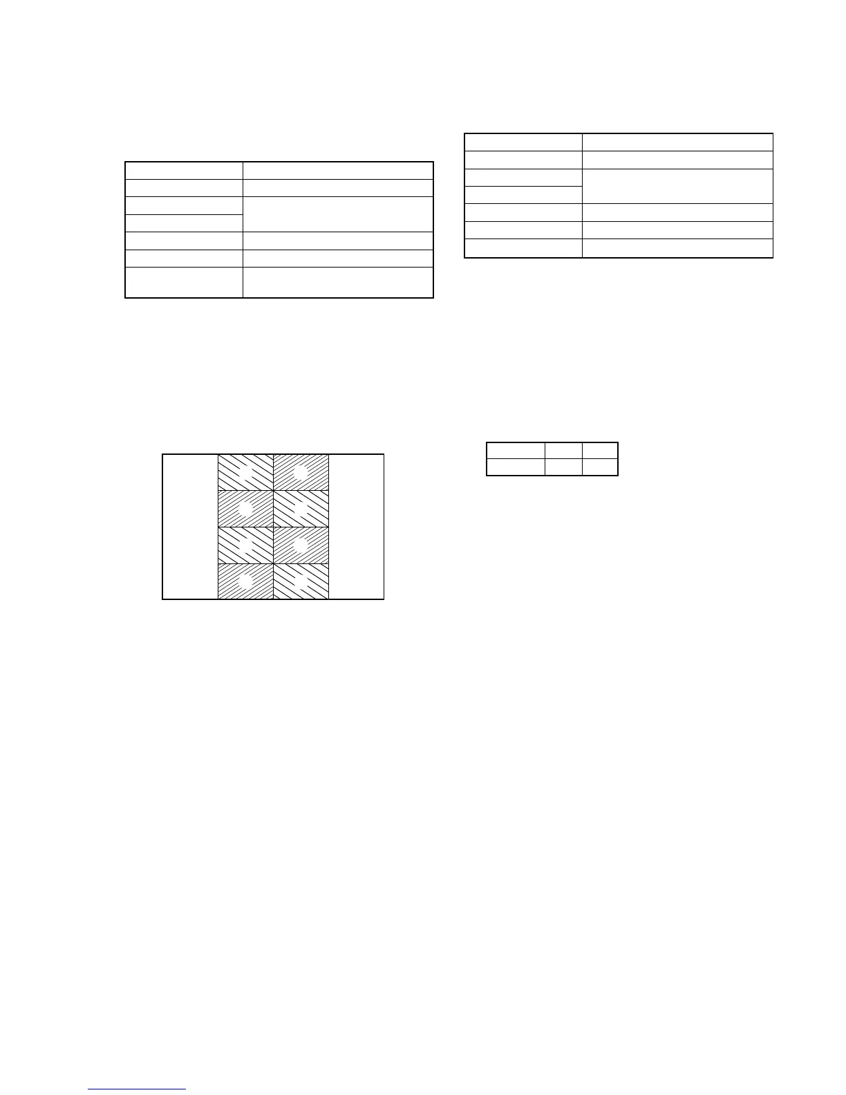
Specified Value The brightness difference between the
section A and section B is minimum.
Note1: Perform “RGB AMP Adjustment”, “Contrast Adjustment” and
“COM AMP Adjustment” before this adjustment.
Adjusting method:
1) Select page: 0, address: 01, and set data: 01.
2) Select page: 7, address: E7, change the data so that the
brightness of the section A and that of the section B is equal.
3) Press the PAUSE button of the adjustment remote commander.
4) Select page: 0, address: 01, and set data: 00.
7. White Balance Adjustment (PD-117 board)
Correct the white balance.
If deviated, the LCD screen color cannot be reproduced.
Mode Camera
Subject Arbitrary
Measurement Point Check on LCD display
Measuring Instrument
Adjustment Page 7
Adjustment Address EB, EC
Specified Value The LCD screen should not be colored.
Note1: Check the white balance only when replacing the following parts.
If necessary, adjust them.
1. LCD panel
2. Light induction plate
3. IC5501
Adjusting method:
1) Select page: 0, address: 01, and set data: 01.
2) Select page: 7, address: EB and EC, and set the data to the
initial value.
Note: To write in the non-volatile memory (EEPROM), press the
PAUSE button of the adjustment remote commander each time
to set the data.
3) Check that the LCD screen is not colored. If colored, change
the data of page: 7, address: EB and EC so that the LCD screen
is not colored.
Note: To write in the non-volatile memory (EEPROM), press the
PAUSE button of the adjustment remote commander each time
to set the data.
4) Select page: 0, address: 01, and set data: 00.
Fig. 5-1-25.
A
A
A
A
B
B
B
B
Address
Data
EB
60
EC
65