5-35
2. VCO Adjustment (PD-117 board)
Set the VCO free-run frequency. If deviated, the LCD screen will
be blurred.
Mode Camera
Subject Arbitrary
Measurement Point Pin 8 of CN5502 (XHD OUT)
Measuring Instrument Frequency counter
Adjustment Page 7
Adjustment Address E5
Specified Value f = 15734 ± 30Hz
Adjusting method:
1) Select page: 0, address: 01, and set data: 01.
2) Select page: 7, address: E5, change the data and set the XHD
OUT frequency (f) to the specified value.
3) Press the PAUSE button of the adjustment remote commander.
4) Select page: 0, address: 01, and set data: 00.
3. RGB AMP Adjustment (PD-117 board)
Set the D range of the RGB decoder used to drive the LCD to the
specified value. If deviated, the LCD screen will become blackish
or saturated (whitish).
Mode Camera
Subject Arbitrary
Measurement Point Pin 3 of CN5502 (VG)
External trigger :
Pin 4 of CN5502 (PANEL COM)
Measuring Instrument Oscilloscope
Adjustment Page 7
Adjustment Address E8
Specified Value LCD TYPE S: A = 3.63 ± 0.05V
LCD TYPE C: A = 3.00 ± 0.05V
Note1: Press the DISPLAY button and erase the screen indictors on the
LCD screen.
Note2: Refer to “LCD type check” for the discrimination of the LCD
type.
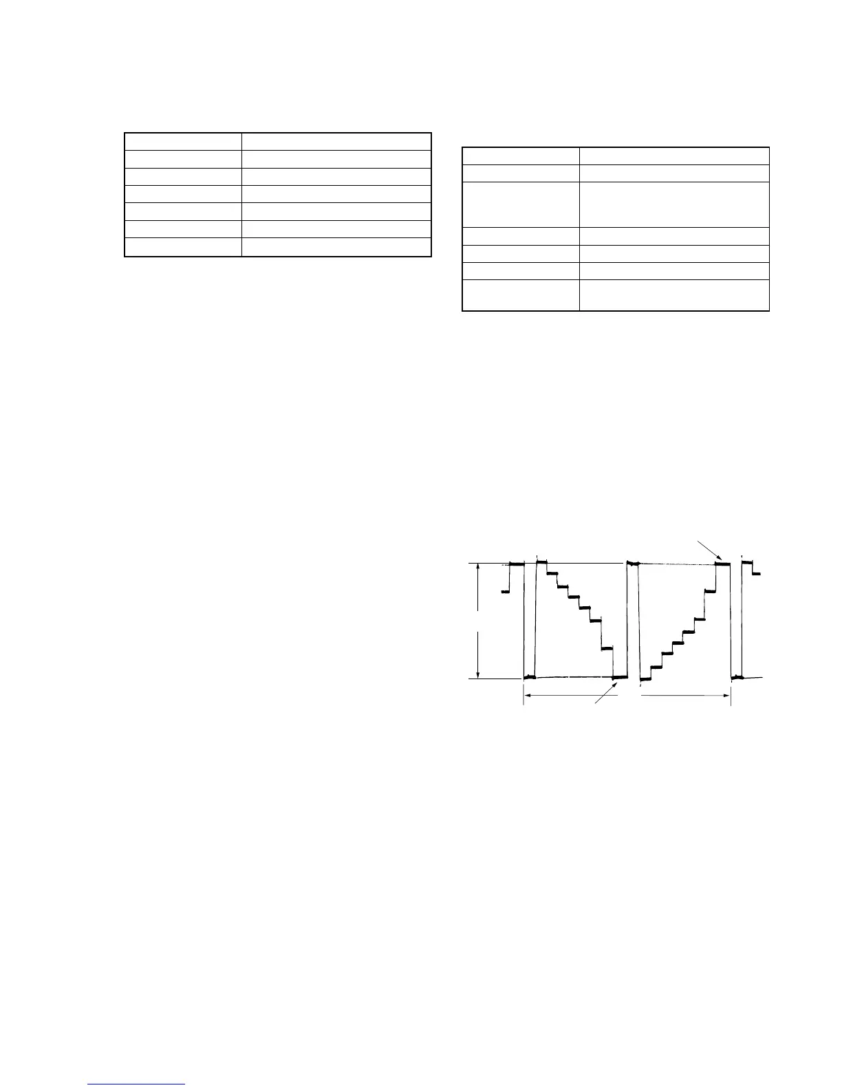
Adjusting method:
1) Select page: 0, address: 01, and set data: 01.
2) Select page: 7, address: E8, change the data and set the voltage
(A) between the reversed waveform pedestal and non-reversed
waveform pedestal to the specified value.
(The data of address: E8 should be “00” to “3F”.)
3) Press the PAUSE button of the adjustment remote commander.
4) Select page: 0, address: 01, and set data: 00.
Fig. 5-1-22.