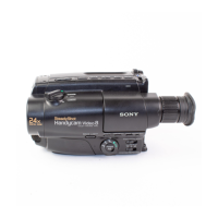
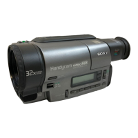
5-46
5. C OUT Level Adjustment (VC-234 board)
Set the chroma signal output level. (Adjust the D/A converter out
put level of IC641.)
Mode VTR stop
Signal No signal
Measurement Point Hi8 model:
Chroma signal terminal of S VIDEO
terminal (75Ω terminated)
Standard8 model:
VIDEO terminal (75Ω terminated)
Measuring Instrument Oscilloscope
Adjustment Page F
Adjustment Address 68
Specified Value A=286 ± 5mV
Note1: Hi8 model:
Insert the plug into the S VIDEO terminal.
Standard8 model:
Insert the plug into the VIDEO terminal.
Note2: Hi8 model:
CCD-TRV67/TRV87/TRV87P
Standard8 model:
CCD-TR317/TR517/TRV17/TRV37/TRV47/TRV57/TRV57P
Adjusting method:
1) Select page: 0, address: 01, and set data: 01.
2) Select page: 2, address: 01, set data: 41, and press the PAUSE
button of the adjustment remote commander.
3) Select page: 6, address: 61, and set data: 30.
4) Select page: F, address: 68, change the data and set the burst
level (A) to the specified value.
5) Press the PAUSE button of the adjustment remote commander.
6) Select page: 6, address: 61, and set data: 10.
7) Select page: 2, address: 01, set data: 00, and press the PAUSE
button of the adjustment remote commander.
8) Select page: 0, address: 01, and set data: 00.
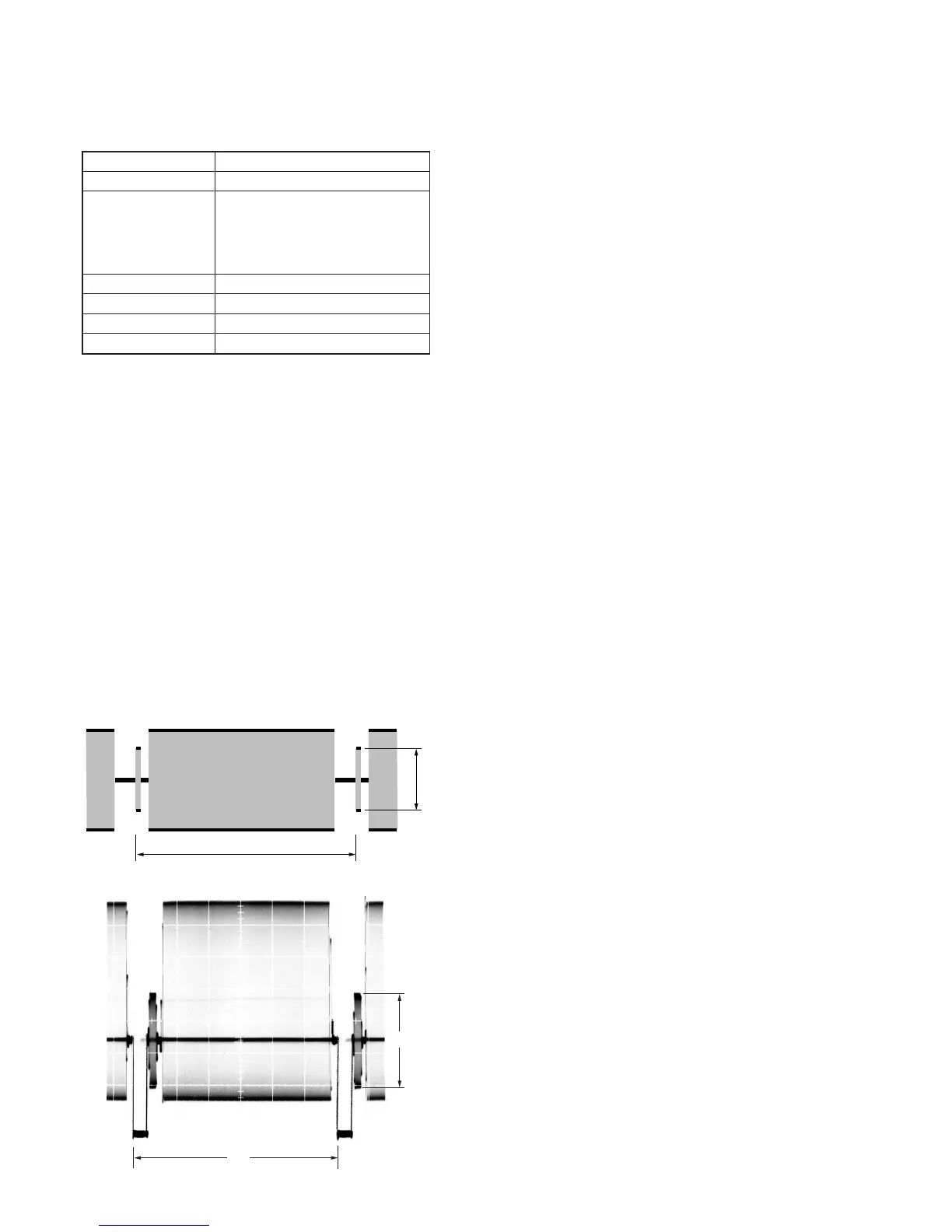
H
A
Fig. 5-3-9.
Hi8 model
Standard8 model
H
A