5-55
3-7. MONAURAL AUDIO SYSTEM ADJUSTMENT
(CCD-TR317/TR517/TRV17/TRV37/TRV47/
TRV57/TRV57P/TRV67)
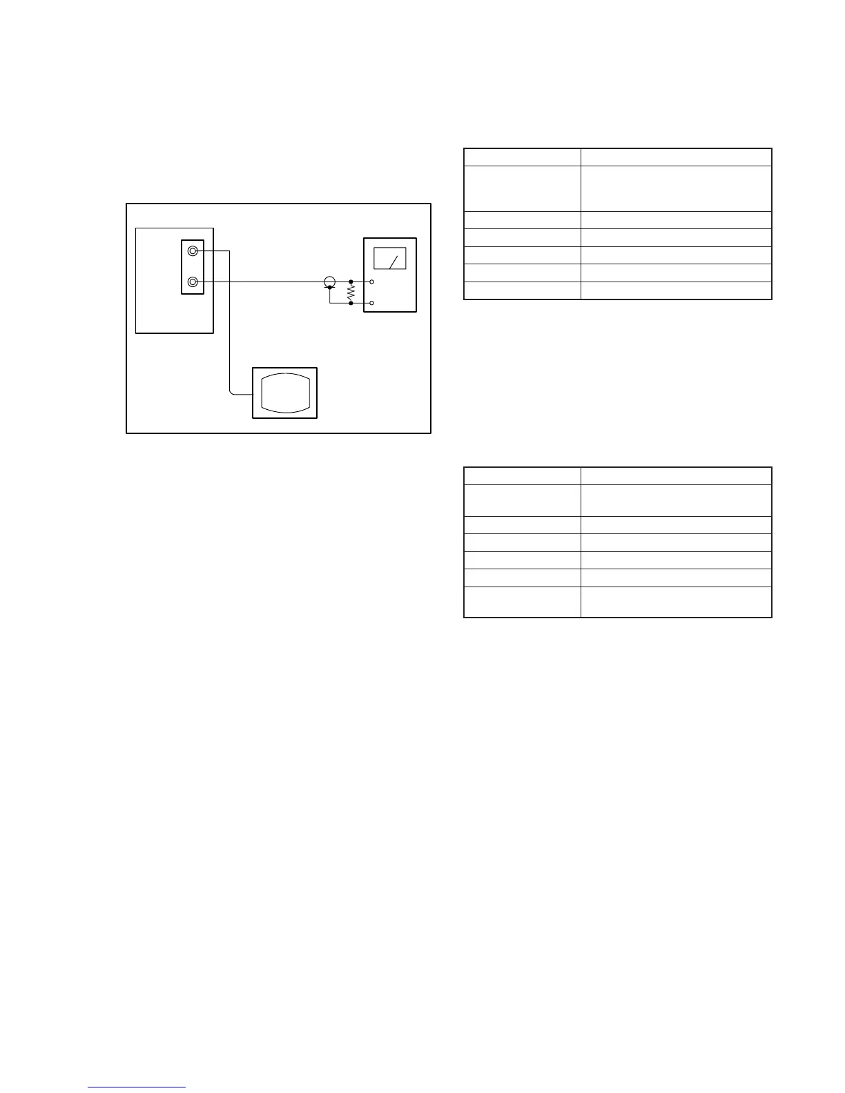
[Connecting the measuring instruments for the audio]
Connect the audio system measuring instruments besides the video
system measuring instruments as shown Fig. 5-3-21.
1. 1.5 MHz Deviation Adjustment (VC-234 board)
Adjust to the optimum audio FM signal deviation.
If the adjustment is not correct, its playback level will differ from
that of other units.
Mode Playback
Signal Alignment tape:
For checking the operation
(WR5-5NSP)
Measurement Point Audio output terminal
Measuring Instrument Audio level meter
Adjustment Page F
Adjustment Address 7B
Specified Value –7.5 ± 0.5dBs
Adjusting method :
1) Select page: 0, address: 01, and set data: 01.
2) Select page: F, address: 7B, change the data and set the 400Hz
signal level to the specified value.
3) Press the PAUSE button of the adjustment remote commander.
4) Select page: 0, address: 01, and set data: 00.
2. BPF Adjustment (VC-234 board)
Adjust to the optimum audio BPF characteristics of the IC.
If the adjustment is not correct, the distortion rate and S/N ratio will
worsen.
Mode Playback
Signal Alignment tape:
For BPF adjustment (WR5-11NS)
Measurement Point Audio output terminal
Measuring Instrument Distortion meter
Adjustment Page F
Adjustment Address 7D
Specified Value The distortion rate should be and
minimum.
Adjusting method :
1) Select page: 0, address: 01, and set data: 01.
2) Select page: F, address: 7D, change the data and minimize the
distortion rate.
3) Press the PAUSE button of the adjustment remote commander.
4) Select page: 0, address: 01, and set data: 00.
Main unit
VIDEO
AUDIO
47k
Ω
47k
Ω
:1-249-437-11
Audio level meter or
distortion meter
TV monitor
Fig. 5-3-21.