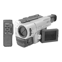
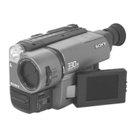
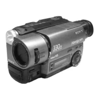
5-28
2. VCO Adjustment (VF-141 board)
Set the VCO free-run frequency. If deviated, the LCD screen will
be blurred.
Mode Camera
Subject Arbitrary
Measurement Point Pin qg of CN982 (VCO) on VC-234
board
Measuring Instrument Frequency counter
Adjustment Page 7
Adjustment Address D5
Specified Value f = 15734 ± 30Hz
Adjusting method:
1) Select page: 0, address: 01, and set data: 01.
2) Select page: 7, address: D5, change the data and set the VCO
frequency (f) to the specified value.
3) Press the PAUSE button of the adjustment remote commander.
4) Select page: 0, address: 01, and set data: 00.
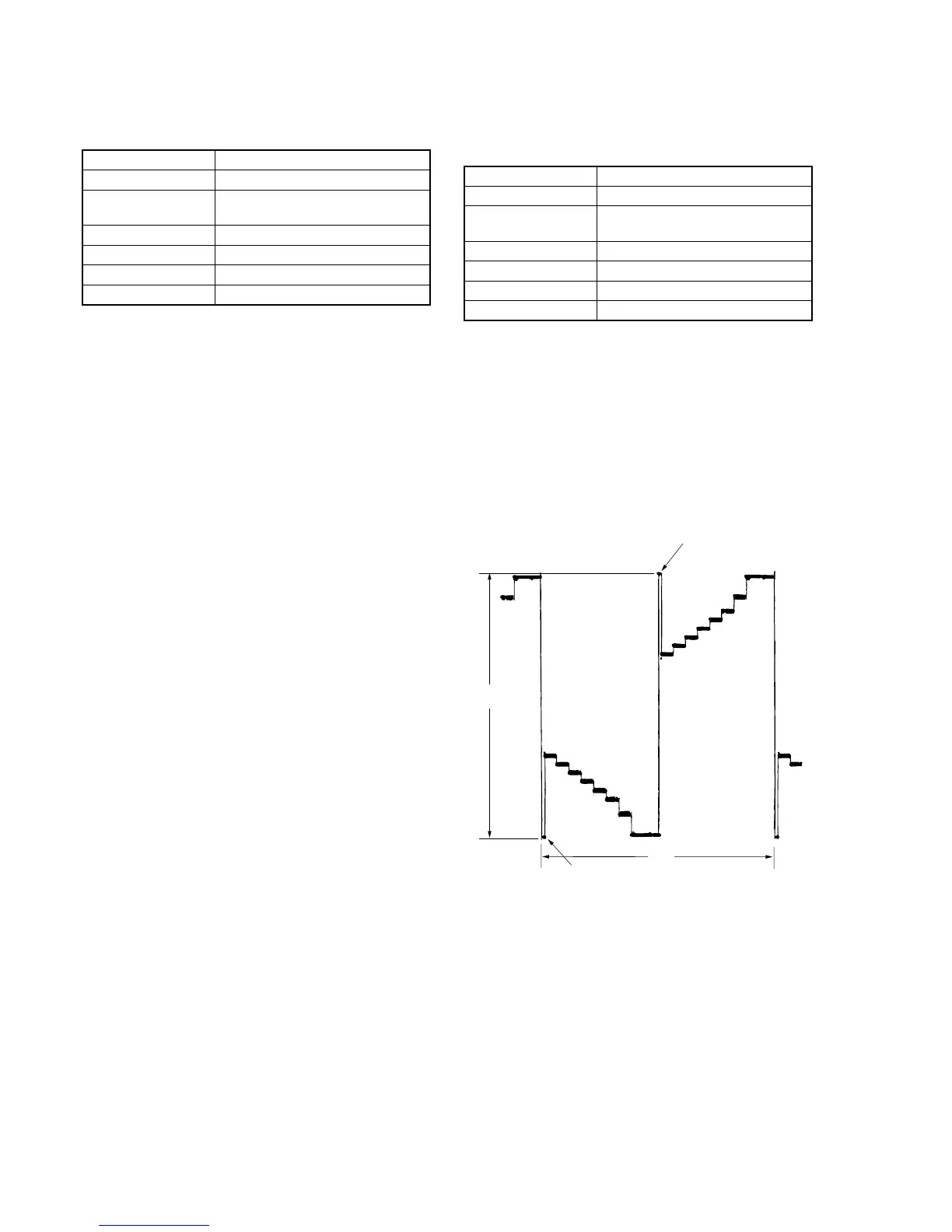
3. RGB AMP Adjustment (VC-141 board)
Set the D range of the RGB decoder used to drive the LCD to the
specified value. If deviated, the LCD screen will become blackish
or saturated (whitish).
Mode Camera
Subject Arbitrary
Measurement Point Pin qh of CN982 (EVF VG) on VC-234
board
Measuring Instrument Oscilloscope
Adjustment Page 7
Adjustment Address D8
Specified Value A = 7.20 ± 0.1V
Adjusting method:
1) Select page: 0, address: 01, and set data: 01.
2) Select page: 7, address: DE, set data: 10, and press the PAUSE
button of the adjustment remote commander.
3) Select page: 7, address: D8, change the data and set the voltage
(A) between the reversed waveform pedestal and non-reversed
waveform pedestal to the specified value.
4) Press the PAUSE button.
5) Select page: 7, address: DE, set data: 90, and press the PAUSE
button.
6) Select page: 0, address: 01, and set data: 00.
Fig. 5-1-14.
Pedestal
Pedestal
A
2H