A-4
DNW-A75/A75P
SV REF
1/2 VD
Time Code
CTL REC (60 Hz)
duty (%)
Color Framing
FR S M H
SW
FR S M H
SW
FR S M H
SW
FR S M H
SW
FR S M H
SW
FR S
25.025 ms
16.68 ms
1234 234121
65 50 50 50 50 50 50
65 6550
525/60 System
SV REF
1/2 VD
Time Code
CTL REC (50 Hz)
duty (%)
Color Framing
FR S M H
SW
FR S M H
SW
FR S M H
SW
FR S M H
SW
FR S M H
SW
FR S
30.00 ms
20.00 ms
1234 678521
65 50 50 50 50 50 50
35 6550
625/50 System
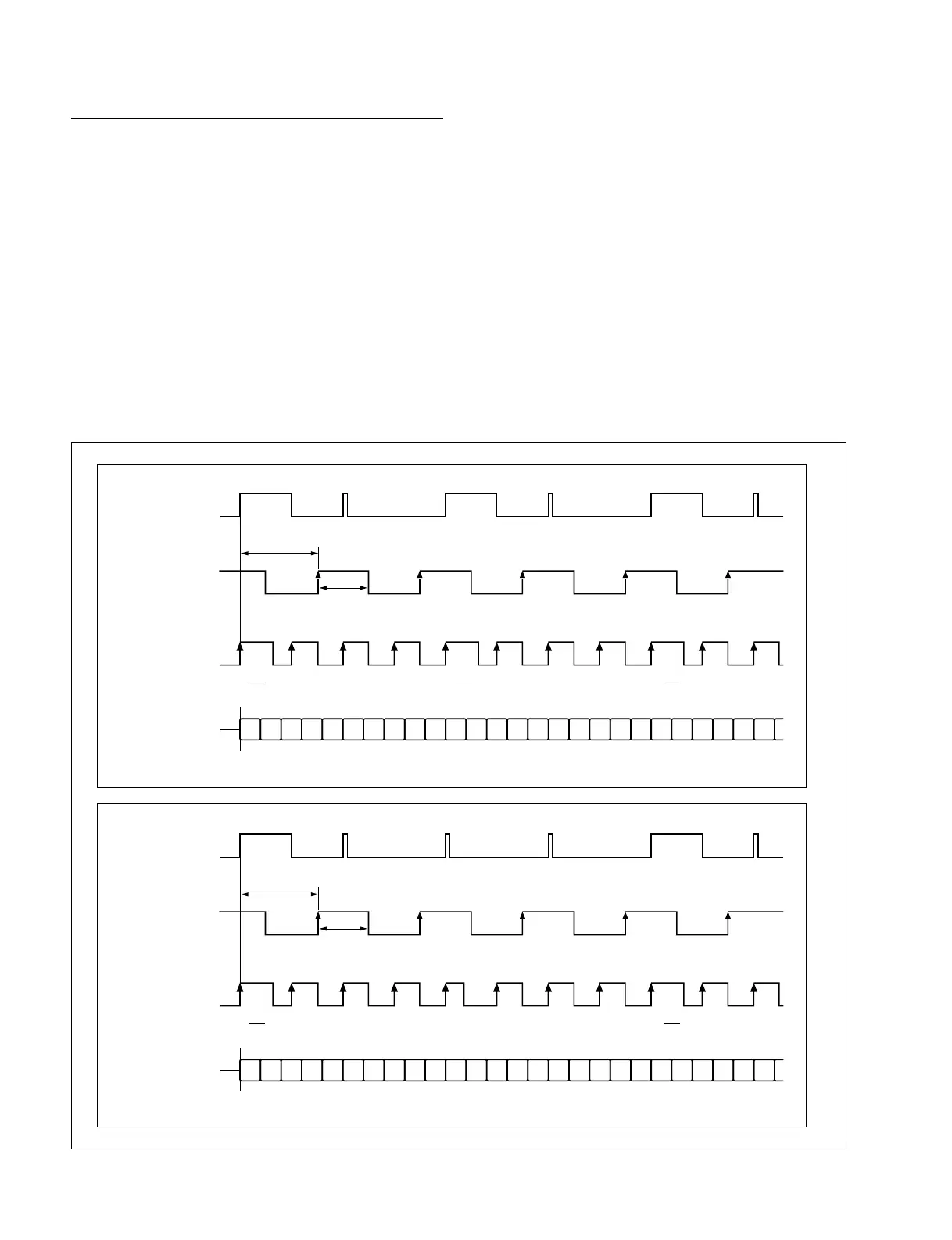
The CTL signal is recorded by approx. 60 Hz (525/60) or
50 Hz (625/50) rectangular pulse system and controls the
start timing of each field data at the rising edge of the
pulse. The CTL signal also modulates the duty cycle of the
rectangular wave to 65:35 in the first field of a color flame
so as to identify the field number and control the color
framing.
The time code signal uses a conventional longitudinal time
code based on the SMPTE/EBU standard.
One flame consists of 80 bits. Flame number, second,
minute, hour, and sync word data items are coded by a
biphase mark coding method and recorded for every flame.
A user bit is written in time data for recording as a binary
group.
Fig. A-2-3. Recording Timing Chart of CTL Signal and Time Code Signal
A-2. Recording Format
Longitudinal Tracks of Betacam SX Format
As shown in Fig. A-2-1, a control track, time code track,
and AUX track are provided in the longitudinal direction
of the tape.
Fig. A-2-3 shows the CTL signal and time code signal, and
the timing relation between these signals and video
reference signals. The top of the figure is for the 525/60
system, the bottom of the figure is for the 625/50 system.