1-14
DNW-A75/A75P
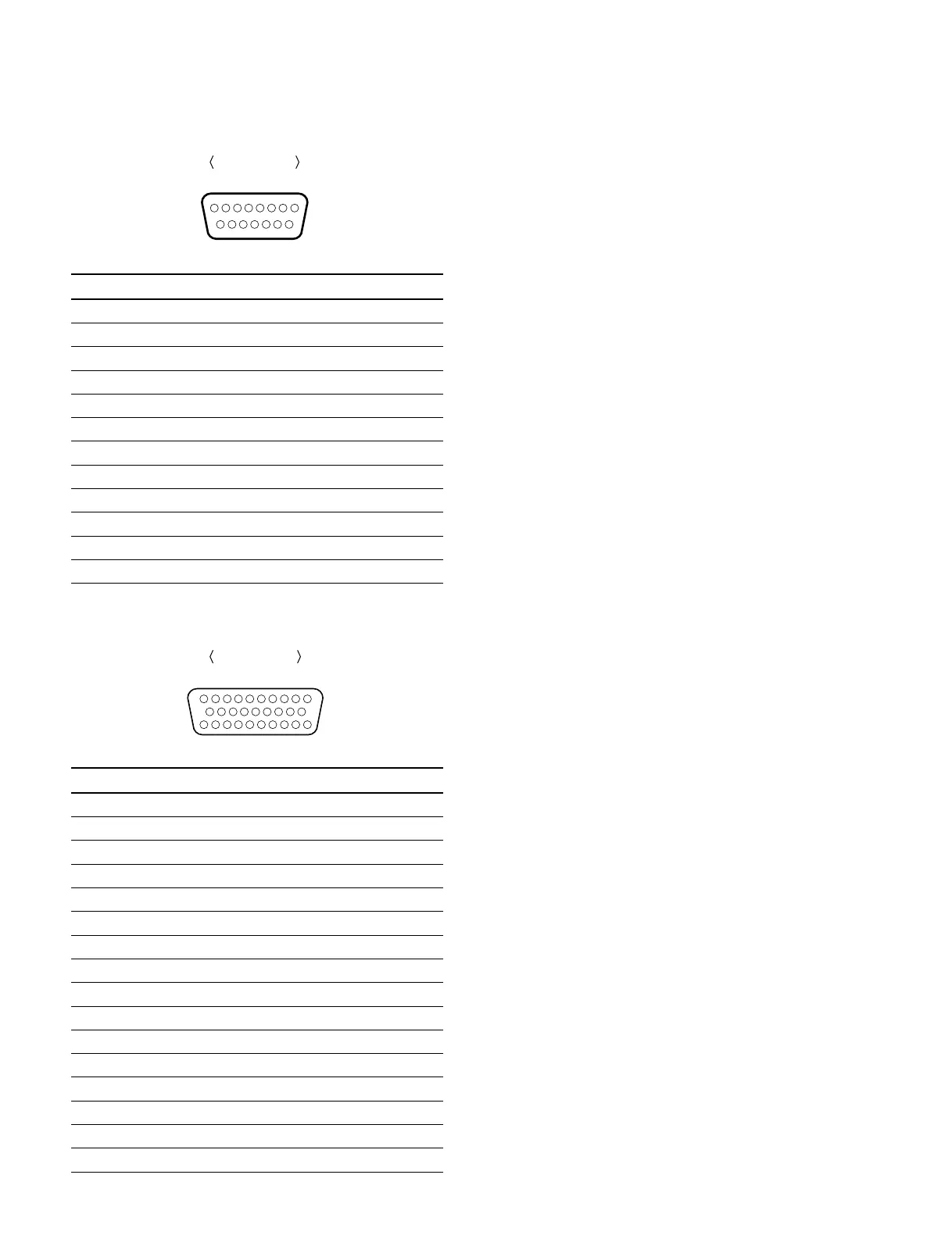
External view
81
915
VIDEO CONTROL: 15-pin (male)
Pin No. Signal Terminal voltage (V)
1 SYNC CONT (Input) _5 to +5
2 HUE CONT (Input) _5 to +5
3 SC CONT (Input) _5 to +5
4 VIDEO LEVEL CONT (Input) _5 to +5
5 SETUP CONT (Input) _5 to +5
6 CHROMA LEVEL CONT (Input) _5 to +5
7 REG _12V (Output) _12
8 GND ——
9 to 12 NC ——
13 Y/C DELAY CONT (Input) _5 to +5
14 NC ——
15 REG +12V (Output) +12
CONTROL PANEL: 29-pin (female)
Pin No. Signal Terminal voltage (V)
1 GND ——
2 KEY RX (_) (Input) RS422
3 KEY TX (+) (Output) RS422
4 GND ——
5 to 7 REG +8V (Output) +8
8, 9 NC ——
10, 11 GND ——
12 KEY RX (+) (Input) RS422
13 KEY TX (_) (Output) RS422
14 GND ——
15 to 17 REG +8V (Output) +8
18 NC ——
19 to 23 GND ——
24 to 26 REG +8V (Output) +8
27, 28 NC ——
29 GND ——-
110
2029
19 11
External view
1-9. Switch Settings on Connector Panel
When the unit is installed, be sure to perform the following
setup.
Refer to the operation manual “Section 2 Location and
Function of Parts” for setup.
. Analog audio input level/600 Z termination switches
. 75 Z termination switch of reference video input
. 75 Z termination switch of composite video input
1-8. Signal Inputs and Outputs
1-9. Switch Settings on Connector Panel