Chapter 9 Maintenance and Troubleshooting
130
Chapter 9 Maintenance and Troubleshooting
Monitor problems
Symptom Cause
Remedy
Data is not superimposed on
the monitor screen.
The CHARACTER switch is set to OFF. Set the CHARACTER switch to ON.
The monitor is not connected to the
VIDEO OUTPUT 2 (SUPER) connector
of this unit.
Connect the monitor to the VIDEO OUTPUT 2
(SUPER) connector. (You must make this
connection to display any type of text on the
monitor.)
The image on the monitor’s
screen is too bright.
The 75 Ω termination switch for video
input on the monitor is in the OFF
position or a 75 Ω terminator is not fitted
to its video input connector.
Set the 75 Ω termination switch to ON or connect
a terminator.
The image on the monitor’s
screen is too dark.
In a video signal loop-through connection
of video monitors, 75 Ω termination
switches for video input on monitors
other than the loop-end monitor are in
the ON position.
Set the 75 Ω termination switches to OFF on all
monitors other than the loop-end monitor .
The image is too dark when
recording a composite video
signal.
Audio problems
Symptom Cause Remedy
The AUDIO INPUT level
adjustment knobs do not work.
The AUDIO INPUT PRESET/VARIABLE
switch is set to PRESET.
Set the AUDIO INPUT PRESET/VARIABLE
switch to VARIABLE.
Sliding the PB AUDIO level
adjustment sliders does not
change the playback audio
output level.
PB AUDIO PRESET/VARIABLE switch
is set to PRESET.
Set the PB AUDIO PRESET/VARIABLE switch to
VARIABLE.
Editing problems
Cause RemedySymptom
Execution of video editing in
insert mode causes subcode
data recorded on tape other
than time code data to
disappear from tape.
This phenomenon cannot be avoided with an editing system
using this unit as the recorder.
Troubleshooting
Chapter 9 Maintenance and Troubleshooting
Chapter 9 Maintenance and Troubleshooting
131
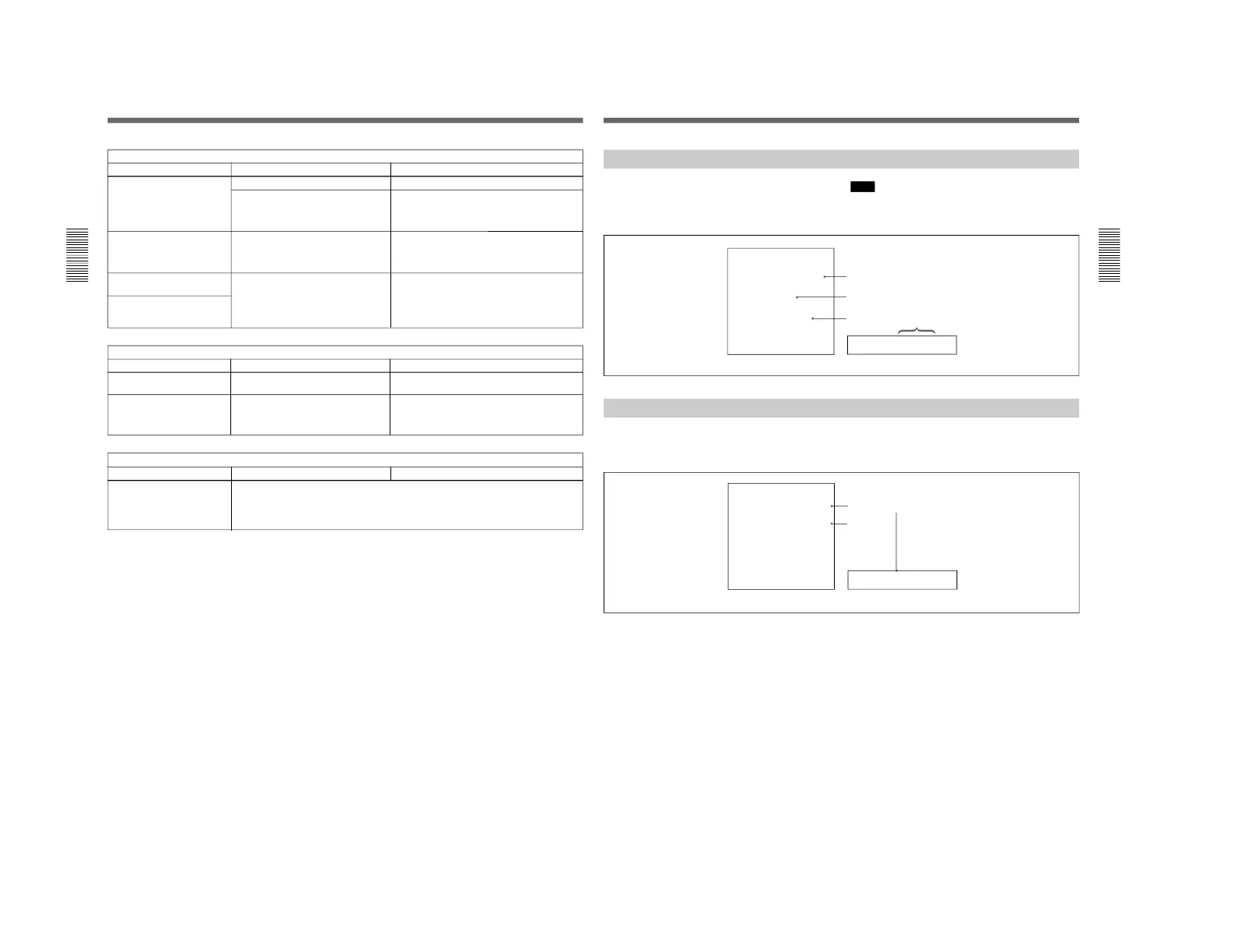
Error Messages
This unit is provided with a self-diagnostic function
that detects internal abnormalities. When it detects an
abnormality, it outputs an error message to the monitor
screen and indicates an error code in the sub LCD.
Note
To display error messages on the monitor screen, set
the CHARACTER switch to ON.
Alarm Messages
Cause of alarm
Direction
Monitor screen Sub LCD
If an alarm message appears, follow the direction
indicated under the message on the monitor screen.
To display alarm messages on the monitor screen, set
the CHARACTER switch to ON, and setup menu item
016 (ALARM) and 106 (REFERENCE SYSTEM
ALARM) to ON or LIMIT.