www.spacelabshealthcare.com
4-7
XPREZZON AND QUBE
O
PERATIONS MANUAL
D ISPLAY OPTIONS
Connectors and Mounting
The setup and maintenance information is contained in the XPREZZON (P/N 070-
2155-xx) or qube (P/N 070-2451-xx) service manuals on the Service CD (P/N 084-
0700-xx)
Connectors
The connectors differ between the 94267-19 and the -L17, -L19, and -L15.
Refer to the Figures for the different connections for each display:
• Display connections for 94267-19 on page 4-7
• Display connections for 94267-L15, 94267-L17, and 94267-L19 on page 4-8.
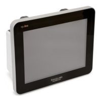
Figure 4-3 Display connections for 94267-19
1 VGA analog in (not used)
2 DVI video in, analog or digital connector
3 Touchscreen serial port
4 Audio in and alarm lights (RJ50)
5 DC Power in (12 VDC)
Equipment connected to the analog or digital interfaces must comply with
the respective IEC standards (e.g. IEC 60950 for data processing equipment
and IEC 60601-1 for medical equipment). Furthermore, all configurations
shall comply with the current version of the standard for SYSTEMS IEC 60601-
1-1. Everybody who connects additional equipment to the signal input part
or signal output part configure a medical system, and is therefore
responsible that the system complies with current version of the
requirements of the system standard IEC 60601-1-1. If in doubt, consult the
technical service department or your local representative.
Before connecting the cables to the flat panel display and Spacelabs
Healthcare monitor, be sure that all components are powered OFF.