Modbus Communication
OXY5500 Operator’s Manual 4
–19
Configuration of an Analog Output
Precondition: Sensor is connected, sensor constants and calibration values
are already set up correctly (OP-9). 4-20mA Output is already in a calibrated
state.
The goal for this configuration is to set up the analog output 1 for a linear
oxygen value output between 10 and 110 ppm gas, with an error level of 2mA.
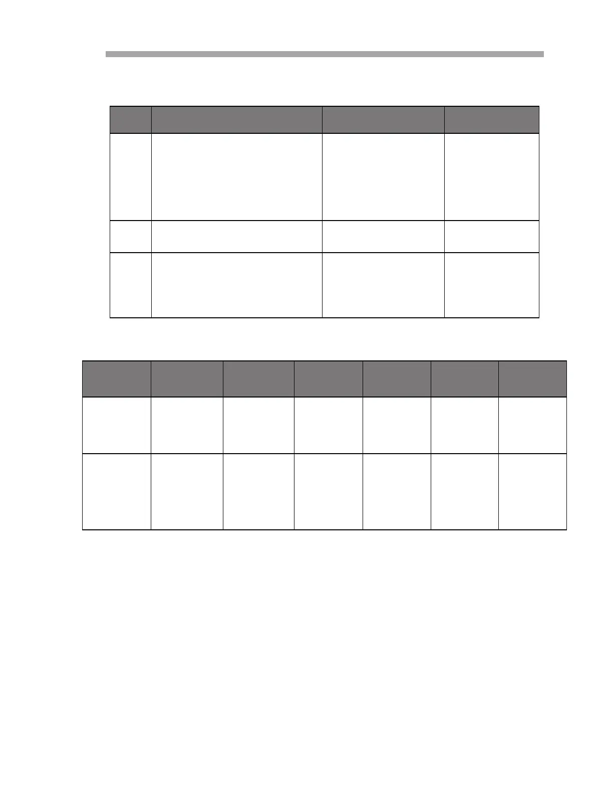
Table 4-17 Configuration for a continuous measurement (Continued)
Step Description Register(s) Value
8 Read measurement control regis-
ter. If bit 1 is deleted, go to step 9.
If bit 1 is set or the display has
timed out, repeat step 7 until it the
value shows ‘0’ (maximum 400 ms.
A time-out detection should be
implemented).
5707, 5708 /
9 Read out the last measurement. 4895 to 4908 Refer to
Table 4–18.
10 Read out the oxygen unit. 2089, 2090 1073741824
(Int32 translates
to 0x40000000
hex, meaning
ppm gas)
Table 4–18 Reading measurement example
Register
4895/4896
Register
4897/4898
Register
4899/4900
Register
4901/4902
Register
4903/4904
Register
4905/4906
Register
4907/4908
Float:
Pressure in
mbar
Float:
Reference
Amplitude
V
Float:
Oxygen
Amplitude in
V
Float:
Oxygen
Phase shift
in degrees
Float:
Tempera-
ture in
C
Float:
Calculated
Oxygen
Value in unit
Int32:
Error Regis-
ter, refer to
Table 4–10.
1006.23 35000.00 (a
value
between 10
and 60000)
10562.12
(Sensor and
environment
dependent
value)
44.32
(Sensor and
environ-
ment depen-
dent value)
20.56 100 (Sen-
sor and
environ-
ment
dependent
value)
0 (Error
code.
Should be 0
if a sensor is
connected)
 Loading...