Oxygen Analyzer
2–8 4900002239 rev. G 3-4-16
Connecting the Analog Outputs/Analog Inputs
The OXY5500 is equipped with two independent analog outputs and one analog
input. The 4-20 mA current loop and serial output are connected terminal
blocks located inside the analyzer electronics enclosure. By default, the 4-
20mA current loop analog outputs (IOUT1/IOUT2) are set to inactive.
The analog outputs are programmable to oxygen and temperature. To allow
external data collection, one input port is available (i.e., external pressure
sensor).
Connections can be made with customer-supplied cables for the current loop
and alarms. Consult the wiring diagram in Figure A–2 on page A–4.
USB Connection: The USB connection is for service and
troubleshooting purposes only. Do not connect during normal
operation. To avoid damage to the port, use only the USB Mini B
cable to connect to the unit.
Ethernet: The unit uses standard Modbus over Ethernet
communication. Use a CAT5 (or better) cable and make
connections per IEEE 802.3 standard.
A protective device (miniature circuit-breaker or circuit breaker)
and a disconnection unit for the power supply must be installed.
SpectraSensors recommends using a line-side miniature circuit
breaker (IEC 898): Characteristic B from 16 A or Characteristic C
from 10 A.
Certified Ex e glands and cables, or conduit seal and conduit,
should be used where appropriate in compliance with local
regulations.
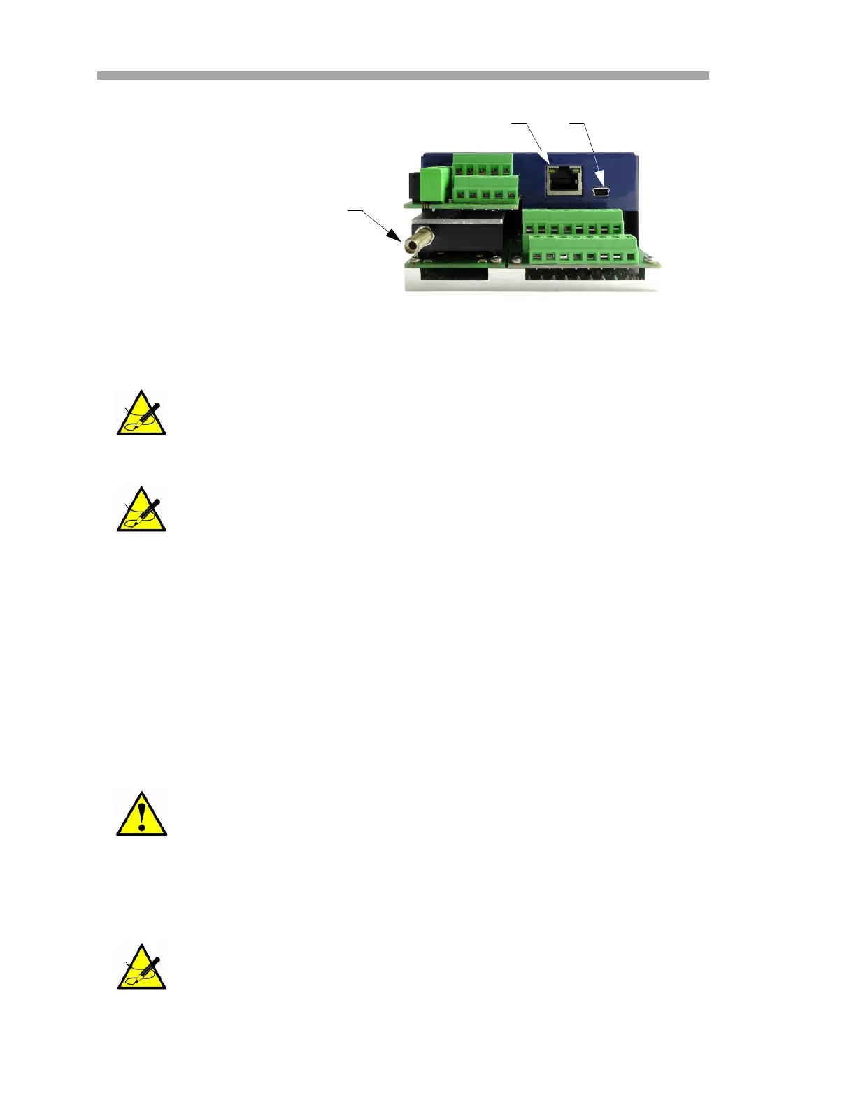
OPTICAL MODULE WITH
SMA CONNECTOR
RJ-45
USB
Figure 2–3 Analyzer connections
 Loading...