Oxygen Analyzer
2–10 4900002239 rev. G 3-4-16
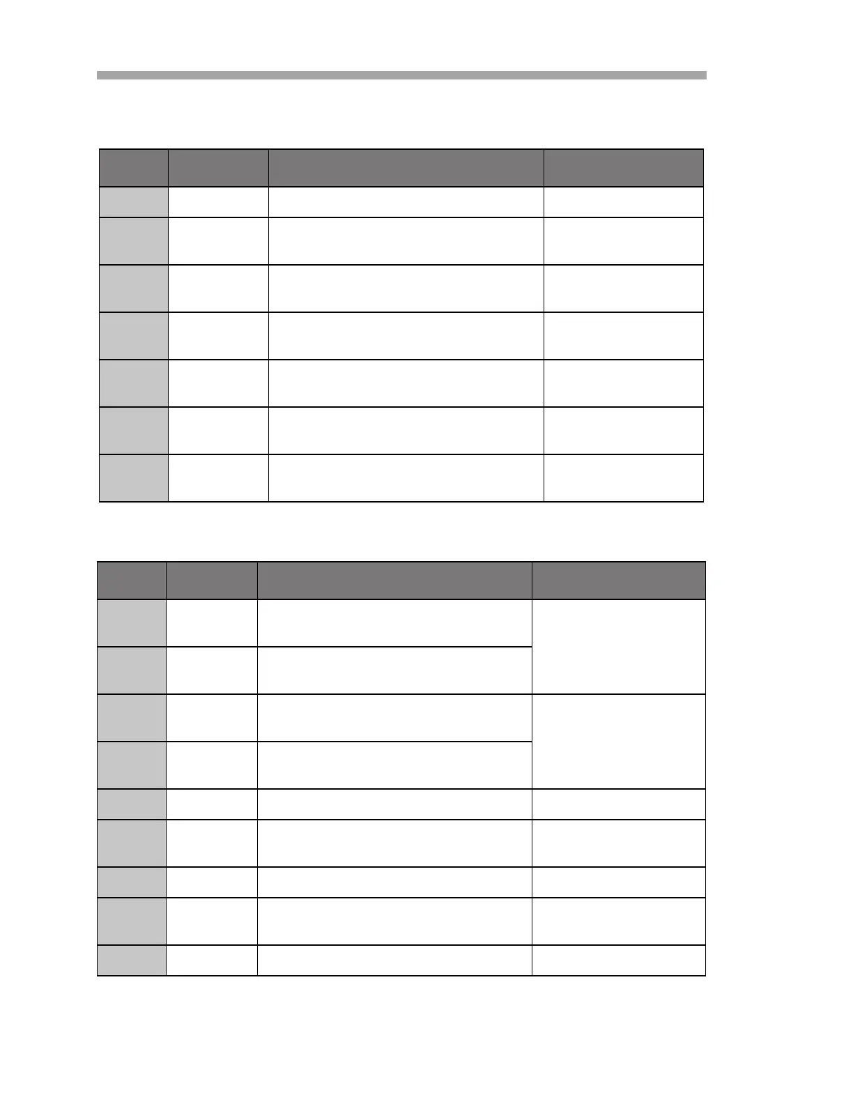
Table 2-1 Terminal Block TB1 (Continued)
Pin Label Description Function
4 GND Power supply GND Power ground
5
232TX RS-232 transmitter output
(typical signal level ± 6 V)
RS-232 signal
transmit
6
232Rx RS-232 receiver input
(typical signal level ± 6 V)
RS-232 signal
receive
7
GND RS-232/RS-485 ground RS-232/RS-485
signal ground
8
GND RS-232/RS-485 ground RS-232/RS-485
signal ground
9
485(A)+ RS-485 non-inverting receiver input
and non-inverting driver output
RS-485 signal
10
485(B)- RS-485 inverting receiver input and
inverting driver output
RS-485 signal
Table 2–2 Terminal Block TB2
Pin Label Description Function
1
L-S1 OptoMOS relays, switch #1
(400V/250mA; R = max 8 Ohm) General Fault Alarm;
normally closed
2
L-S1 OptoMOS relays, switch #1
(400V/250mA; R = max 8 Ohm)
3
L-S2 OptoMOS relays, switch #2
(400V/250mA; R = max 8 Ohm) Concentration Alarm;
normally closed
4
L-S2 OptoMOS relays, switch #2
(400V/250mA; R = max 8 Ohm)
5 GNDA Analog ground Analog ground
6
IOUT1 Analog output 1 (4 – 20 mA); max
load = 800 Ohm
Analog output
7 GNDA Analog ground Analog ground
8
1
1. The 4-20 mA outputs are configured as sourcing to provide power to the loop. If a
PLC/HMI is used to provide power to the loop, an isolator will be required.
IOUT2 Analog output 2 (4 – 20 mA); max
load = 800 Ohm
Analog output
9 NC Not connected
 Loading...